|
|
| (35 intermediate revisions by 2 users not shown) |
| Line 1: |
Line 1: |
| − | ==Calling through PA System==
| + | {{A}} |
| − | [[Image:FIG FBSAR 1 1.png|thumb|350px|Figure 1.1 Calling through PA System]] | + | The AlphaCom can be interfaced to PA Amplifiers via the [[FBSAR]] board. The amplifier is connected via the FBSAR board to an [[ASLT]] subscriber line. The PA amplifier is called simply by dialing the [[directory number]] of the FBSAR. [[Groups#Group_Call.2FAnnouncements|Group calls]] will be distributed via the PA amplifier if the FBSAR is member of the group. It is possible to send entertainment or emergency audio from the [[Audio Program|audio program inputs]] out via the FBSAR, as well as [[Voice Alarm Messages|alarm messages]] from the [[ASVP]] board. |
| | | | |
| − | ===Feature Description=== | + | ==Connections== |
| − | The AlphaCom can distribute audio through separate loudspeakers for announcements and music distribution. This audio can be distributed via an FBSAR board. When loudspeakers without amplification are used, there must not be more than 20 such loudspeakers in one system. Such loudspeakers can only be connected via a FBSAR board. | + | The FBSAR board provides two independent interfaces, channel 1 and channel 2. Channel 1 has 0dBm audio output with volume control, and a relay for switching the amplifier on when audio is present. Channel 2 has 0dBm audio output, but no volume control and no relay. |
| | | | |
| − | ===Equipment List=== | + | There are four jumpers on the FBSAR, S1 to S4, they should all be set in the "down" position (2-3). |
| − | * PA system / additional loudspeakers | + | ===Channel 1=== |
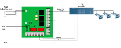
| − | * Filter Board with Speech Adapter [[FBSAR]] 1009505000 | + | *Connect the CH1 connector to a free [[ASLT]] subscriber port with a-, b-, c- and d-wires. |
| − | * [[PDB - Power Distribution Board|Power Distribution Board PDB 1009970100]] (This Board is only required in an E26 installation. E7 and E20 has +24VDC outputs.) | + | *The 0 dBm audio signal from the FBSAR is connected to the line input of the amplifier. If the amplifier is not VOX controlled, the relay contact is connected to an input on the amplifier for switching the amplifier on when audio is present. |
| − | <br/> | + | *If the relay is used, a RCO signal is required and the FBSAR must be [[Powering Additional Equipment|powered by 24VDC from the exchange]]. |
| − | One FBSAR can feed two speakers or two PA amplifiers from two subscriber lines.
| + | *The potentiometer VOL OUT on the FBSAR allows you to adjust the output signal level |
| | + | [[Image:FBSAR PA amplifier.png|left|thumb|500px|Interface to PA amplifier via channel 1]] |
| | + | <br style="clear:both;" /> |
| | | | |
| − | ===Installation=== | + | ===Channel 2=== |
| − | ====Installing the FBSAR board====
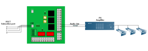
| + | *Connect the CH2 connector to a free [[ASLT]] subscriber port with a-, b-, c- and d-wires. |
| − | * Fasten the FBSAR board onto one of the mounting rails on the distribution field. | + | *The 0 dBm audio signal from the FBSAR is connected to the line input of the amplifier. |
| − | * Supply the board with 24 V and 0 V (GND) from the Power Distribution Board or other source of power. Use a 1-pair ordinary installation cable for this purpose; the cable is not supplied with the board. | + | [[Image:FBSAR PA amplifier ch2.png|left|thumb|500px|Interface to PA amplifier via channel 2]] |
| − | * Run the wires according to Figure 1.1.
| + | <br style="clear:both;" /> |
| − | * Check the [[FBSAR#Connectors_and_Switches|switch settings]].
| |
| − | <br/> | |
| | | | |
| − | ===Additional information=== | + | ==RCO Operation== |
| − | If you use the FBSAR for the connection no programming in necessary. We do however recommend that you program the physical connection for the PA system as a substation.
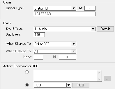
| + | The relay of the FBSAR is controlled by a [[RCO]]. The RCO is configured in the [[Event Handler]]. In the '''Users & Stations''' window, highlight the FBSAR in the list box, and select the button '''Events'''. Press '''Insert''' to create an event with the following parameters (here RCO 1 is used as an example): |
| − | <br/>
| + | [[File:Application_A3a.png|500px|left|thumb|Event for operating the RCO]] |
| − | <br/> | + | <br style="clear:both;" /> |
| | | | |
| − | ==Amplified Calling Through Loudspeaker without Answer Option==
| + | Press the button "Details" to select which type of audio that should trigger the RCO (Sub Event 126 means all types of audio). |
| − | [[Image:FBSAR PA 2.JPG|thumb|350px|Figure 2.1 Amplified Calling Through Loudspeaker without Answer Option]]
| |
| − | ===Feature Description===
| |
| − | You use a loudspeaker for voice distribution of incoming calls. You may also choose to have distribution of group calls and audio programs through the loudspeaker. Additional indication of incoming calls may be connected.
| |
| | | | |
| − | ===Equipment List===
| |
| − | * AlphaCom System with desired station range
| |
| − | * Additional loudspeakers
| |
| − | * Filter Board with Speech Adapter FBSAR 10099505000
| |
| − | * [[PDB - Power Distribution Board|Power Distribution Board PDB 1009970100]] (This Board is only required in an E26 installation. E7 and E20 has +24VDC outputs.)
| |
| − | * Power Amplifier WK1000614100
| |
| − | * Mounting box
| |
| − | * Local power supply for the Power Amplifier
| |
| − | * PC with [[AlphaPro]] program and cable for connection to the AlphaCom exchange
| |
| | | | |
| − | ===Installation===
| + | [[Category: Public Address - Features and configuration]] |
| − | | + | [[Category: AlphaCom Applications]] |
| − | ====Installing the FBSAR board====
| |
| − | * Fasten the FBSAR board onto one of the mounting rails on the distribution field.
| |
| − | * Supply the board with 24 V and 0 V (GND) from the Power Distribution Board or other source of power. Use an 1-pair ordinary installation cable for this purpose. The cable is not supplied with the board.
| |
| − | * Run the wires according to Figure 2.1 Amplified Calling through loudspeaker without answer option. Audio and RCO output connections are done from the Subscriber Connection board.
| |
| − | * Make sure the [[FBSAR#Connectors_and_Switches|switches]] are in the correct positions.
| |
| − | S1: 1-2
| |
| − | S2: 1-2
| |
| − | S3: 1-2 Channel 1
| |
| − | 2-3 Channel 2
| |
| − | S4: 2-3 (AlphaCom)
| |
| − | | |
| − | ====Installing the Power Amplifier====
| |
| − | * Mount the board in a mounting box near the amplified loudspeaker
| |
| − | * Install a local power supply
| |
| − | * Connect the cables according to Figure 2.1 Amplified Calling through loudspeaker without answer option
| |
| − | <br/>
| |
| − | <br/>
| |
| − | | |
| − | ==Station with Amplified Calling and Answer through the Station using Amplifier WK20==
| |
| − | [[Image:FBSAR PA 3.JPG|thumb|350px|Figure 3.1 Station with Amplified Calling and Answer through the Station using Amplifier WK20]]
| |
| − | | |
| − | ===Feature Description===
| |
| − | The loudspeaker amplifies the calling tones, private ringing tone and canceling tones. When the calling station uses the M-key, the amplifier is switched on and off. When a key on the amplified station is touched or the handset is lifted, the amplifier is switched off.
| |
| − | | |
| − | ===Equipment List===
| |
| − | * AlphaCom System with desired station range
| |
| − | * Filter Board with Speech Adapter FBSAR 1009505000
| |
| − | * Power Amplifier WK1000614100
| |
| − | * [[PDB - Power Distribution Board|Power Distribution Board PDB 1009970100]] (This Board is only required in an E26 installation. E7 and E20 has +24VDC outputs.)
| |
| − | * Additional Loudspeaker
| |
| − | * PC with AlphaPro program and cable for connection to the AlphaCom exchange.
| |
| − | | |
| − | ===Installation===
| |
| − | | |
| − | ====Installing the Power Distribution Board====
| |
| − | * See [[PDB - Power Distribution Board]]
| |
| − | If a PDB board is already installed, you need not switch off the entire exchange. Just unplug the connector on the PDB board supplying power from the exchange.
| |
| − | '''''CAUTION'''''
| |
| − | Do not extend power cables from the PDB outside the exchange rack environment.
| |
| − | Use local power for remote installation of equipment.
| |
| − | | |
| − | ====Installation of FBSAR board====
| |
| − | * Fasten the FBSAR board onto one of the mounting rails on the distribution field.
| |
| − | * Supply the board with 24 V and 0 V (GND) from the Power Distribution Board. Use a 1-pair ordinary installation cable for this purpose. The cable is not supplied with the board.
| |
| − | * Run the wires according to the drawing below. Audio and RCO output connections are done from the Subscriber Connection board.
| |
| − | * Make sure the [[FBSAR_-_PA_interface#Switch_settings|switches]] are in the correct positions.
| |
| − | | |
| − | ====Installing the Power Amplifier====
| |
| − | * Mount the board in a mounting box near the amplified loudspeaker
| |
| − | * Install a local power supply
| |
| − | * Connect the cables according to Figure 3.1 Amplified Calling with answer in the station.
| |
The AlphaCom can be interfaced to PA Amplifiers via the FBSAR board. The amplifier is connected via the FBSAR board to an ASLT subscriber line. The PA amplifier is called simply by dialing the directory number of the FBSAR. Group calls will be distributed via the PA amplifier if the FBSAR is member of the group. It is possible to send entertainment or emergency audio from the audio program inputs out via the FBSAR, as well as alarm messages from the ASVP board.
Connections
The FBSAR board provides two independent interfaces, channel 1 and channel 2. Channel 1 has 0dBm audio output with volume control, and a relay for switching the amplifier on when audio is present. Channel 2 has 0dBm audio output, but no volume control and no relay.
There are four jumpers on the FBSAR, S1 to S4, they should all be set in the "down" position (2-3).
Channel 1
- Connect the CH1 connector to a free ASLT subscriber port with a-, b-, c- and d-wires.
- The 0 dBm audio signal from the FBSAR is connected to the line input of the amplifier. If the amplifier is not VOX controlled, the relay contact is connected to an input on the amplifier for switching the amplifier on when audio is present.
- If the relay is used, a RCO signal is required and the FBSAR must be powered by 24VDC from the exchange.
- The potentiometer VOL OUT on the FBSAR allows you to adjust the output signal level

Interface to PA amplifier via channel 1
Channel 2
- Connect the CH2 connector to a free ASLT subscriber port with a-, b-, c- and d-wires.
- The 0 dBm audio signal from the FBSAR is connected to the line input of the amplifier.

Interface to PA amplifier via channel 2
RCO Operation
The relay of the FBSAR is controlled by a RCO. The RCO is configured in the Event Handler. In the Users & Stations window, highlight the FBSAR in the list box, and select the button Events. Press Insert to create an event with the following parameters (here RCO 1 is used as an example):

Event for operating the RCO
Press the button "Details" to select which type of audio that should trigger the RCO (Sub Event 126 means all types of audio).


