Difference between revisions of "Unlock two doors using one station"
From Zenitel Wiki
(→Testing) |
(→Connections) |
||
| (14 intermediate revisions by 2 users not shown) | |||
| Line 1: | Line 1: | ||
| − | It is possible to use a single [[ | + | {{AI}} |
| + | It is possible to use a single [[:Category:Stations#Turbine_stations|Turbine IP station]] to unlock two (or more) different doors independently of each other. Each door has a single access digit that unlocks only that door. | ||
| + | |||
| + | The main thing is to set the Turbine station as "Station Type" = '''PNCI'''. When in conversation with the Turbine, digits dialed during the conversation will not trigger any feature in the ICX-AlphaCom, but the digits will be reported in the Event Handler, event 25. | ||
In the manner described in this article, the Turbine has a potential to control seven devices using the single built-in relay and six I/O ports. For practicality and clarity, the examples show only two devices being controlled – one with the built-in relay and one with an I/O port. For control of more devices, simply expand the setup and programming to the other I/O ports. If using the Turbine extended, there are two relays + 6 I/O's available. | In the manner described in this article, the Turbine has a potential to control seven devices using the single built-in relay and six I/O ports. For practicality and clarity, the examples show only two devices being controlled – one with the built-in relay and one with an I/O port. For control of more devices, simply expand the setup and programming to the other I/O ports. If using the Turbine extended, there are two relays + 6 I/O's available. | ||
| Line 10: | Line 13: | ||
==Connections== | ==Connections== | ||
| − | To use the Turbine inbuilt relay, connect the first set of lock control wires to the Common and NO (Normally Open) connection points (Note: Ground is NOT Common). The numbered connection ports (1-6) on the back of the Turbine correspond to I/O ports 1-6. To use any of the Turbines six I/O ports, connect the external relay board trigger wires to the connectors labeled +5 and one of the labeled connectors 1, 2,3,4,5 or 6, based on which output port will be used. Output wires from the relay board run on to the second lock control device | + | To use the Turbine inbuilt relay, connect the first set of lock control wires to the Common and NO (Normally Open) connection points (Note: Ground is NOT Common). The numbered connection ports (1-6) on the back of the Turbine correspond to I/O ports 1-6. To use any of the Turbines six I/O ports, connect the external relay board trigger wires to the connectors labeled +5 and one of the labeled connectors 1, 2,3,4,5 or 6, based on which output port will be used. Output wires from the relay board run on to the second lock control device. |
| − | + | See also [[Adding additional relay(s) to a Zenitel IP Device]]. | |
| − | + | ||
| + | {{Note|+5 is used as the common so that when the output is active it will be +5VDC and when not active the output will be 0VDC.}} | ||
| − | + | {{Note|It is assumed here that the external relay logical trigger will be 1 (ON) to close the contact. Rarely, some external relays may expect 0VDC to trigger. If this condition is encountered, move the lead from +5VDC to 0VDC. This will cause the normal state of the I/O port to be +5VDC and the active state to be 0VDC in effect reversing normal logic controls.}} | |
| − | |||
| − | |||
| − | |||
| − | |||
| − | |||
This example uses the built-in relay and I/O port 2: | This example uses the built-in relay and I/O port 2: | ||
| Line 27: | Line 26: | ||
==Turbine Setup== | ==Turbine Setup== | ||
| − | All IP stations require a two-part setup procedure – one part in the station and the other using the [[AlphaPro]] programming tool. It is assumed here that the station is already configured and operational with the AlphaCom system. What follows are the changes needed to allow relay and I/O functions. | + | All IP stations require a two-part setup procedure – one part in the station and the other using the [[AlphaPro]] programming tool. It is assumed here that the station is already configured and operational with the ICX-AlphaCom system. What follows are the changes needed to allow relay and I/O functions. |
===StationWeb=== | ===StationWeb=== | ||
| − | Login to the Turbine station and select '''Advanced AlphaCom'''. Select '''I/O Settings''' and in the line titled '''I/O Pin 2''' choose '''Output 2''' in the dropdown '''Configuration''' box. Next select '''Save | + | Login to the Turbine station and select '''Advanced ICX-AlphaCom'''. Select '''I/O Settings''' and in the line titled '''I/O Pin 2''' choose '''Output 2''' in the dropdown '''Configuration''' box. Next select '''Save''' followed by '''Reboot'''.. |
| − | + | [[File:Application25l.png|500px|left|thumb|]] | |
| − | |||
| − | |||
| − | |||
| − | |||
| − | |||
| − | [[File: | ||
<br style="clear:both;" /> | <br style="clear:both;" /> | ||
| − | + | This concludes the in-station portion of the configuration. | |
==AlphaPro Programming== | ==AlphaPro Programming== | ||
| Line 50: | Line 43: | ||
===Exchange Setup=== | ===Exchange Setup=== | ||
| − | [[RCO - Remote Control Output|Remote Control Outputs]] (RCO) are one method the AlphaCom uses to control external devices. These logical outputs associate an output signal to a particular device. In the example two RCOs will be associated with one Turbine station. | + | [[RCO - Remote Control Output|Remote Control Outputs]] (RCO) are one method the ICX-AlphaCom uses to control external devices. These logical outputs associate an output signal to a particular device. In the example two RCOs will be associated with one Turbine station. |
| − | From AlphaPro select the first tab, '''Exchange and Settings'''. | + | From AlphaPro select the first tab, '''Exchange and Settings'''. |
| + | [[File:Application25b.png|500px|left|thumb|]] | ||
| + | <br style="clear:both;" /> | ||
| − | [[File: | + | Choose the '''RCO''' Button. |
| + | [[File:Application25c.png|500px|left|thumb|]] | ||
<br style="clear:both;" /> | <br style="clear:both;" /> | ||
From the '''Remote Control Outputs''' window select an unused RCO (RCO 1 in the example) then '''Change''' | From the '''Remote Control Outputs''' window select an unused RCO (RCO 1 in the example) then '''Change''' | ||
| − | + | [[File:Application25d.png|500px|left|thumb|]] | |
| − | [[File: | ||
<br style="clear:both;" /> | <br style="clear:both;" /> | ||
On the '''Update Records''' window change the '''Description''' so it will be obvious that this RCO is in use. The '''RCO Type''' box should be set to '''Station''' and the '''Station''' box should contain the '''''physical''''' number of the station (3 for directory 103 in the example). '''Pin Number''' is always dependent on the type of station being used. In the example a Turbine station is being used and the pin for the '''''relay''''' on a Turbine is always '''7'''. Select '''OK''' when finished. | On the '''Update Records''' window change the '''Description''' so it will be obvious that this RCO is in use. The '''RCO Type''' box should be set to '''Station''' and the '''Station''' box should contain the '''''physical''''' number of the station (3 for directory 103 in the example). '''Pin Number''' is always dependent on the type of station being used. In the example a Turbine station is being used and the pin for the '''''relay''''' on a Turbine is always '''7'''. Select '''OK''' when finished. | ||
| − | + | [[File:Application25e.png|500px|left|thumb|]] | |
| − | [[File: | ||
<br style="clear:both;" /> | <br style="clear:both;" /> | ||
Now return to the '''Remote Control Outputs''' window and select a second unused RCO. Again, select '''Change''' and enter an appropriate description. As before, the '''RCO Type''' will be '''Station''' and the '''Station''' box will contain the same physical station number as entered earlier (3 in the example). The '''Pin Number''' will match the physical connection on the Turbine I/O connectors, 1 through 6 (2 in the example). Select '''OK''' when finished. | Now return to the '''Remote Control Outputs''' window and select a second unused RCO. Again, select '''Change''' and enter an appropriate description. As before, the '''RCO Type''' will be '''Station''' and the '''Station''' box will contain the same physical station number as entered earlier (3 in the example). The '''Pin Number''' will match the physical connection on the Turbine I/O connectors, 1 through 6 (2 in the example). Select '''OK''' when finished. | ||
| − | + | [[File:Application25f.png|500px|left|thumb|]] | |
| − | [[File: | ||
<br style="clear:both;" /> | <br style="clear:both;" /> | ||
===Master Station Setup=== | ===Master Station Setup=== | ||
Select the '''[[Users & Stations (AlphaPro)|Users and Stations]]''' menu tab in AlphaPro. Find the '''Directory''' number of the master station (102 in the example) which will be unlocking the doors or gates and highlight it. On the '''General''' tab find the '''Station Type''' box and select '''PNCI''' from the dropdown list. Then select '''OK'''. | Select the '''[[Users & Stations (AlphaPro)|Users and Stations]]''' menu tab in AlphaPro. Find the '''Directory''' number of the master station (102 in the example) which will be unlocking the doors or gates and highlight it. On the '''General''' tab find the '''Station Type''' box and select '''PNCI''' from the dropdown list. Then select '''OK'''. | ||
| − | + | [[File:Application25g.png|500px|left|thumb|]] | |
| − | [[File: | ||
<br style="clear:both;" /> | <br style="clear:both;" /> | ||
| − | Next select the '''[[Exchange_%26_System_(AlphaPro)#Events|Events button]]''' | + | Next select the '''[[Exchange_%26_System_(AlphaPro)#Events|Events button]]''' and create a new event. '''When Related To''' is the calling station (directory number 103 in the example). Multiple calling stations will require multiple like events (i.e. one event for each calling station). |
| − | + | [[File:Application25a.png|500px|left|thumb|]] | |
| − | [[File: | ||
<br style="clear:both;" /> | <br style="clear:both;" /> | ||
| − | + | {{Code2| | |
| − | + | IF %op(%sev,<nowiki>=</nowiki>,6) if 6 is dialed | |
| − | + | RCO 1 ON 30 turn on RCO 1 for 3 seconds | |
| − | IF %op(%sev,=,6) | + | ENDIF |
| − | RCO 1 ON 30 | + | IF %op(%sev,<nowiki>=</nowiki>,7) if 7 is dialed |
| − | ENDIF | + | RCO 2 ON 30 turn on RCO 2 for 3 seconds |
| − | + | ENDIF | |
| − | IF %op(%sev,=,7) | + | }} |
| − | RCO 2 ON 30 | ||
| − | ENDIF | ||
| − | |||
| − | |||
===Ringing Group Setup=== | ===Ringing Group Setup=== | ||
This procedure requires that any master station releasing the door be in a Ringing Group. Without being in a Ringing Group the relay and I/O activation will only work if the master initiates the call. The Ringing Group allows the master to unlock the door regardless of who initiated the call. | This procedure requires that any master station releasing the door be in a Ringing Group. Without being in a Ringing Group the relay and I/O activation will only work if the master initiates the call. The Ringing Group allows the master to unlock the door regardless of who initiated the call. | ||
| − | Select the '''Group''' icon and then '''Local Groups''' to bring up the Groups window. | + | Select the '''Group''' icon and then '''Local Groups''' to bring up the Groups window. |
| + | [[File:Application25h.png|500px|left|thumb|]] | ||
| + | <br style="clear:both;" /> | ||
| − | [[File: | + | Highlight '''Ringing Group 1''' and then select '''Change''' |
| + | [[File:Application25i.png|500px|left|thumb|]] | ||
<br style="clear:both;" /> | <br style="clear:both;" /> | ||
| − | |||
| − | [[File: | + | Select the '''Members''' tab and then move the desired master station (102 in the example) to the '''Members''' box by clicking on the right arrow button. |
| + | [[File:Application25j.png|500px|left|thumb|]] | ||
<br style="clear:both;" /> | <br style="clear:both;" /> | ||
| + | |||
The substation must now call the Ringing Group just configured. Return to the '''Users and Stations''' menu and find the Turbine substation being used (103 in the example). Select the '''[[DAK]]''' (Direct Access Key) menu button. In the DAK Programming window, each numbered line corresponds to a call button. When the button is pressed it will call the directory number shown on the line associated with that button. The example substation, like most substations, has only one call button. On line 1 enter directory number '''6701''' (corresponds to the directory number of Ringing Group 1). The system will insert an “i” in front of the number entered. Select '''OK''' when finished. When the button is pressed a call will be made to 6701 (every station in Ringing Group 1). | The substation must now call the Ringing Group just configured. Return to the '''Users and Stations''' menu and find the Turbine substation being used (103 in the example). Select the '''[[DAK]]''' (Direct Access Key) menu button. In the DAK Programming window, each numbered line corresponds to a call button. When the button is pressed it will call the directory number shown on the line associated with that button. The example substation, like most substations, has only one call button. On line 1 enter directory number '''6701''' (corresponds to the directory number of Ringing Group 1). The system will insert an “i” in front of the number entered. Select '''OK''' when finished. When the button is pressed a call will be made to 6701 (every station in Ringing Group 1). | ||
| + | [[File:Application25k.png|500px|left|thumb|]] | ||
| + | <br style="clear:both;" /> | ||
| − | |||
| − | |||
| − | This concludes the AlphaPro portion of the setup. Send the changes to the AlphaCom exchange (server) using the Send '''Change icon'''. After the changes are sent, reset the exchange by using the '''Reset''' icon. | + | This concludes the AlphaPro portion of the setup. Send the changes to the ICX-AlphaCom exchange (server) using the Send '''Change icon'''. After the changes are sent, reset the exchange by using the '''Reset''' icon. |
==Testing== | ==Testing== | ||
| Line 125: | Line 116: | ||
Testing is complete. Wiring from the Turbine built-in relay may now be connected to the first door lock and wiring from the Turbine I/O port may be connected to the external relay board and then on to the second door lock. | Testing is complete. Wiring from the Turbine built-in relay may now be connected to the first door lock and wiring from the Turbine I/O port may be connected to the external relay board and then on to the second door lock. | ||
| − | [[Category: Applications]] | + | |
| + | [[Category: AlphaCom Applications]] | ||
| + | [[Category: ICX-AlphaCom Applications]] | ||
Latest revision as of 15:21, 23 June 2023
It is possible to use a single Turbine IP station to unlock two (or more) different doors independently of each other. Each door has a single access digit that unlocks only that door.
The main thing is to set the Turbine station as "Station Type" = PNCI. When in conversation with the Turbine, digits dialed during the conversation will not trigger any feature in the ICX-AlphaCom, but the digits will be reported in the Event Handler, event 25.
In the manner described in this article, the Turbine has a potential to control seven devices using the single built-in relay and six I/O ports. For practicality and clarity, the examples show only two devices being controlled – one with the built-in relay and one with an I/O port. For control of more devices, simply expand the setup and programming to the other I/O ports. If using the Turbine extended, there are two relays + 6 I/O's available.
Contents
Hardware
An IP Turbine and at least one external relay (such as the Zenitel Multi-Relay Board (MRBD)) is required. A third party relay board must be able to accept a logical input (5vdc or 0vdc) to trigger the relay. A master station with LCD screen and dialing pad is also be required.
For testing, a multi-meter that can read both Ohms and Volts (VDC) is needed.
Connections
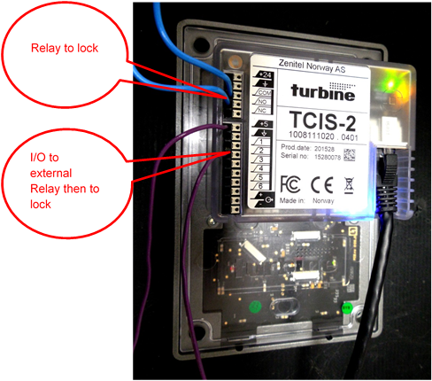
To use the Turbine inbuilt relay, connect the first set of lock control wires to the Common and NO (Normally Open) connection points (Note: Ground is NOT Common). The numbered connection ports (1-6) on the back of the Turbine correspond to I/O ports 1-6. To use any of the Turbines six I/O ports, connect the external relay board trigger wires to the connectors labeled +5 and one of the labeled connectors 1, 2,3,4,5 or 6, based on which output port will be used. Output wires from the relay board run on to the second lock control device.
See also Adding additional relay(s) to a Zenitel IP Device.

|
+5 is used as the common so that when the output is active it will be +5VDC and when not active the output will be 0VDC. |
This example uses the built-in relay and I/O port 2:
Turbine Setup
All IP stations require a two-part setup procedure – one part in the station and the other using the AlphaPro programming tool. It is assumed here that the station is already configured and operational with the ICX-AlphaCom system. What follows are the changes needed to allow relay and I/O functions.
StationWeb
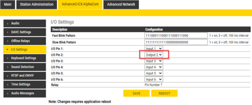
Login to the Turbine station and select Advanced ICX-AlphaCom. Select I/O Settings and in the line titled I/O Pin 2 choose Output 2 in the dropdown Configuration box. Next select Save followed by Reboot..
This concludes the in-station portion of the configuration.
AlphaPro Programming
It is assumed that a working configuration for all intercoms already exists in AlphaPro. Stations should already be able to call and converse with each other. Only the changes needed to activate the relay and I/O ports are discussed.
A master station with dialing pad and LCD screen must be used as the station that will send the digits to unlock each door/gate.
This procedure requires Ringing Groups. Any master that will unlock the doors or gates must be in a Ringing Group. Even if there is only one master, it must be in a Ringing Group. From this, it follows that older systems without Ringing Groups, or systems where Ringing Groups have been removed, will not be able to use this procedure.
Exchange Setup
Remote Control Outputs (RCO) are one method the ICX-AlphaCom uses to control external devices. These logical outputs associate an output signal to a particular device. In the example two RCOs will be associated with one Turbine station.
From AlphaPro select the first tab, Exchange and Settings.
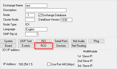
Choose the RCO Button.
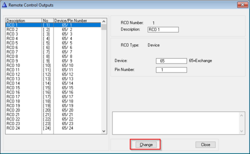
From the Remote Control Outputs window select an unused RCO (RCO 1 in the example) then Change
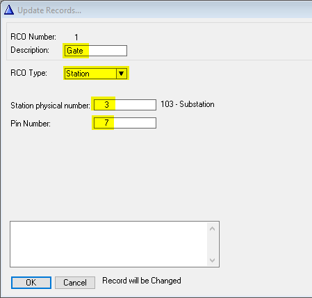
On the Update Records window change the Description so it will be obvious that this RCO is in use. The RCO Type box should be set to Station and the Station box should contain the physical number of the station (3 for directory 103 in the example). Pin Number is always dependent on the type of station being used. In the example a Turbine station is being used and the pin for the relay on a Turbine is always 7. Select OK when finished.
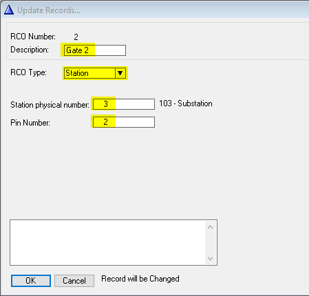
Now return to the Remote Control Outputs window and select a second unused RCO. Again, select Change and enter an appropriate description. As before, the RCO Type will be Station and the Station box will contain the same physical station number as entered earlier (3 in the example). The Pin Number will match the physical connection on the Turbine I/O connectors, 1 through 6 (2 in the example). Select OK when finished.
Master Station Setup
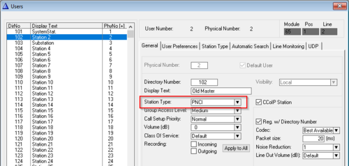
Select the Users and Stations menu tab in AlphaPro. Find the Directory number of the master station (102 in the example) which will be unlocking the doors or gates and highlight it. On the General tab find the Station Type box and select PNCI from the dropdown list. Then select OK.
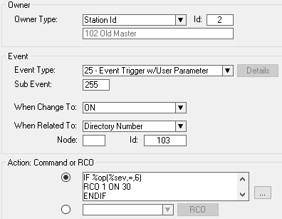
Next select the Events button and create a new event. When Related To is the calling station (directory number 103 in the example). Multiple calling stations will require multiple like events (i.e. one event for each calling station).
Action commands:
IF %op(%sev,=,6)    	if 6 is dialed
RCO 1 ON 30		turn on RCO 1 for 3 seconds
ENDIF
IF %op(%sev,=,7)	if 7 is dialed
RCO 2 ON 30		turn on RCO 2 for 3 seconds
ENDIF
Ringing Group Setup
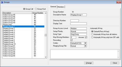
This procedure requires that any master station releasing the door be in a Ringing Group. Without being in a Ringing Group the relay and I/O activation will only work if the master initiates the call. The Ringing Group allows the master to unlock the door regardless of who initiated the call.
Select the Group icon and then Local Groups to bring up the Groups window.
Highlight Ringing Group 1 and then select Change
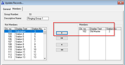
Select the Members tab and then move the desired master station (102 in the example) to the Members box by clicking on the right arrow button.
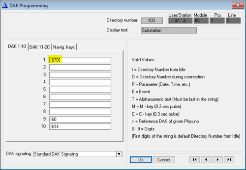
The substation must now call the Ringing Group just configured. Return to the Users and Stations menu and find the Turbine substation being used (103 in the example). Select the DAK (Direct Access Key) menu button. In the DAK Programming window, each numbered line corresponds to a call button. When the button is pressed it will call the directory number shown on the line associated with that button. The example substation, like most substations, has only one call button. On line 1 enter directory number 6701 (corresponds to the directory number of Ringing Group 1). The system will insert an “i” in front of the number entered. Select OK when finished. When the button is pressed a call will be made to 6701 (every station in Ringing Group 1).
This concludes the AlphaPro portion of the setup. Send the changes to the ICX-AlphaCom exchange (server) using the Send Change icon. After the changes are sent, reset the exchange by using the Reset icon.
Testing
After the exchange finishes rebooting, the system is ready to test. Connect an Ohmmeter to the relay connectors (Com and NO) on the Turbine. Connect a Voltmeter to the +5VDC and I/O number 2 connectors (connector 2 if following the example, otherwise whichever I/O connector is being used).
Place a call to the master (102 in the example) by pressing the call button on the Turbine (103 in the example). Answer the call by pressing the M key on the master. Press the digit 6 on the master. For 3 seconds the Ohmmeter should display very little resistance indicating the relay contacts have closed. Press digit 7. The Voltmeter should read +5VDC for 3 seconds indicating a logical ON condition. Cancel the call by pressing C.
From the master station dial 103 (the Turbine in the example). The Turbine will automatically answer. Repeat the above tests by pressing 6 and then 7 to activate the relay and the I/O port respectively. Press C when finished.
Testing is complete. Wiring from the Turbine built-in relay may now be connected to the first door lock and wiring from the Turbine I/O port may be connected to the external relay board and then on to the second door lock.


