AlphaCom XE20: Difference between revisions
From Zenitel Wiki
No edit summary |
|||
| Line 1: | Line 1: | ||
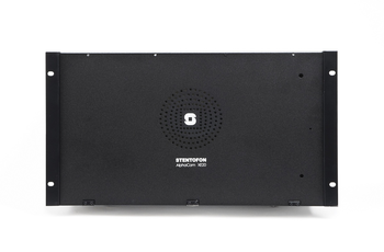
[[Image:XE20.PNG|thumb|350px|AlphaCom XE20 Audio Server with HD Voice]] | [[Image:XE20.PNG|thumb|350px|AlphaCom XE20 Audio Server with HD Voice]] | ||
== Highlights == | ===<u>Highlights</u>=== | ||
* Made to provide critical communication in any environment | * Made to provide critical communication in any environment | ||
* Supports 552 IP stations and 102 analog intercom stations | * Supports 552 IP stations and 102 analog intercom stations | ||
* SIM card based software configuration and disaster recovery | * SIM card based software configuration and disaster recovery | ||
* Fully compatible with any AlphaCom system | * Fully compatible with any AlphaCom system | ||
= | ===<u>[http://www.zenitel.com/product/alphacom-xe20 Additional Documentation on Zenitel.com]</u>=== | ||
== Installation == | ===<u>Installation</u>=== | ||
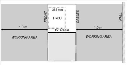
* Up to 4 units may be mounted in one 19” rack if sufficient ventilation is provided. It is recommended to mount a 24 VDC cooling fan module on top of each exchange unit | * Up to 4 units may be mounted in one 19” rack if sufficient ventilation is provided. It is recommended to mount a 24 VDC cooling fan module on top of each exchange unit | ||
[[image:AC E20 Installation.jpg|thumb|500px|left|Mounting AlphaCom XE20]] | [[image:AC E20 Installation.jpg|thumb|500px|left|Mounting AlphaCom XE20]] | ||
<br style="clear:both;" /> | <br style="clear:both;" /> | ||
== Connections == | ===<u>Connections</u>=== | ||
[[File:XE20 Connections.PNG|thumb|left|500px]] | |||
<br style="clear:both;" /> | |||
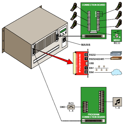
* The exchange is powered from the mains. | |||
* The two-pair star wired intercom cables are connected to connection boards on the cabinet DIN rail or in a separate distribution field | * The two-pair star wired intercom cables are connected to connection boards on the cabinet DIN rail or in a separate distribution field | ||
* Each [[ASLT|subscriber line card]] provides 6 freely programmable Remote Control Outputs ([[RCO]]) | * Each [[ASLT|subscriber line card]] provides 6 freely programmable Remote Control Outputs ([[RCO]]) | ||
* Two RJ-45 Ethernet terminals on the [[Filter card AMC-IP|IP filter board]] are used for IP LAN and WAN communication | * Two RJ-45 Ethernet terminals on the [[Filter card AMC-IP|IP filter board]] are used for IP LAN and WAN communication | ||
* 6 [[Audio Program|program distribution]] sources can be connected to the [[APC - AlphaCom Program & Clock Board|APC board]] via an optional program connection board. Up to 64 extra programs may be added using AGA boards with 16 programs per board | * 6 [[Audio Program|program distribution]] sources can be connected to the [[APC - AlphaCom Program & Clock Board|APC board]] via an optional program connection board. Up to 64 extra programs may be added using AGA boards with 16 programs per board | ||
* The [[Filter card APC|optional program connection]] board has input for 6 Remote Control Inputs ([[RCI]]) which can initiate programmed actions | * The [[Filter card APC|optional program connection]] board has input for 6 Remote Control Inputs ([[RCI]]) which can initiate programmed actions | ||
* The | * The serial ports with RS232 and RS422/RS485 interfaces are used for connecting to equipment using these protocols. Eth0 is also used for programming | ||
[[File:XE20 | |||
====Serial Ports==== | |||
Serial Port 0 - RJ45 (RS232 Only) | |||
:No additional settings necessary | |||
---- | |||
Serial Port 1 - RJ45 (RS232/422/485) | |||
:Additional settings: | |||
:'''RS232:''' | |||
:* [[AMC-IP_-_AlphaCom_Processor_Board_(Red)#Switches_and_jumpers|Switch 8 on S601]] on the AMC-IP board must be set to OFF. | |||
:'''RS422:''' | |||
:* [[AMC-IP_-_AlphaCom_Processor_Board_(Red)#Switches_and_jumpers|Switch 8 on S601]] on the AMC-IP board must be set to ON. | |||
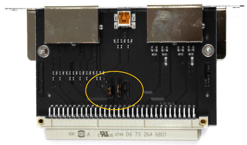
:* Set the two jumpers on the AMC-IP [[Filter card AMC-IP|Filterboard]] to the correct position. | |||
[[File:SerialPortJumpers XE20 26.png|thumb|left|500px|RS422/485 selector for Serial Port 1 on the XE20 AMC-IP Filterboard]] | |||
<br style="clear:both;" /> | <br style="clear:both;" /> | ||
[[Category:AlphaCom Servers]] | [[Category:AlphaCom Servers]] | ||
Revision as of 14:00, 3 November 2016
Highlights
- Made to provide critical communication in any environment
- Supports 552 IP stations and 102 analog intercom stations
- SIM card based software configuration and disaster recovery
- Fully compatible with any AlphaCom system
Additional Documentation on Zenitel.com
Installation
- Up to 4 units may be mounted in one 19” rack if sufficient ventilation is provided. It is recommended to mount a 24 VDC cooling fan module on top of each exchange unit
Connections
- The exchange is powered from the mains.
- The two-pair star wired intercom cables are connected to connection boards on the cabinet DIN rail or in a separate distribution field
- Each subscriber line card provides 6 freely programmable Remote Control Outputs (RCO)
- Two RJ-45 Ethernet terminals on the IP filter board are used for IP LAN and WAN communication
- 6 program distribution sources can be connected to the APC board via an optional program connection board. Up to 64 extra programs may be added using AGA boards with 16 programs per board
- The optional program connection board has input for 6 Remote Control Inputs (RCI) which can initiate programmed actions
- The serial ports with RS232 and RS422/RS485 interfaces are used for connecting to equipment using these protocols. Eth0 is also used for programming
Serial Ports
Serial Port 0 - RJ45 (RS232 Only)
- No additional settings necessary
Serial Port 1 - RJ45 (RS232/422/485)
- Additional settings:
- RS232:
- Switch 8 on S601 on the AMC-IP board must be set to OFF.
- RS422:
- Switch 8 on S601 on the AMC-IP board must be set to ON.
- Set the two jumpers on the AMC-IP Filterboard to the correct position.


