Pulse System Configuration: Difference between revisions
From Zenitel Wiki
| Line 421: | Line 421: | ||
* Script Events | * Script Events | ||
'''''Note''': The Virtual I/O feature requires that the Pulse server must be a [[Turbine|Turbine station]] with [[Pulse Licensing|Pulse Enterprise license]]'' | '''''Note''': The Virtual I/O feature requires that the Pulse server must be a [[:Category:Turbine|Turbine station]] with [[Pulse Licensing|Pulse Enterprise license]]'' | ||
=== Script Upload === | === Script Upload === | ||
Revision as of 13:23, 10 January 2017
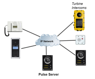
Pulse is an IP-based intercom system for upto 16 intercoms. The system works with all VINGTOR-STENTOFON IP intercoms. Pulse is available in two versions: Pulse Basic and Pulse Enterprise. Pulse Enterprise is only valid with Turbine intercoms.
Pulse Basic includes licensing for:
- SIP Phone
- Telephony
- VS-Client
Pulse Enterprise, in addition to the above, also includes licensing for:
- SDK/API
- Multi-Site Trunking
- Advanced Audio
- Virtual I/O
The Vingtor-Stentofon Intercom Manager Tool (VS-IMT) can be used to configure multiple intercoms in a network. The following sections describe configuration procedures using the web interface of the station.
Define the Pulse Server
One of the intercom stations must be set as the "Pulse Server". The Pulse Server is acting as a server for the other intercom stations in the system. Any station can be a Pulse Server. However, more features are available if a Turbine station is acting as a Pulse Server. There must be only one Pulse Server in the installation.
Connect the LAN port of the station to be the Pulse Server to a PoE Ethernet switch. Do not connect any other stations at this point.
Logging into the Station
Ensure that the IP address of your PC is in the same range as that of the station IP address. Access the station by logging into the web interface using a standard web browser on your PC:
- 1. Open a web browser
- 2. In the browser’s address bar, type the station IP address and press the ENTER key
- - The station login page will be displayed.
To log into the station:
- 1. Click Login
- 2. Enter the default User name: admin
- 3. Enter the default password: alphaadmin
The Station Information page will now be displayed, showing the IP station configuration and status.
Note that the user interface and parameters displayed in the following sections are dependent on the Turbine station type (Compact, Industrial or Ex) selected.
Main Settings
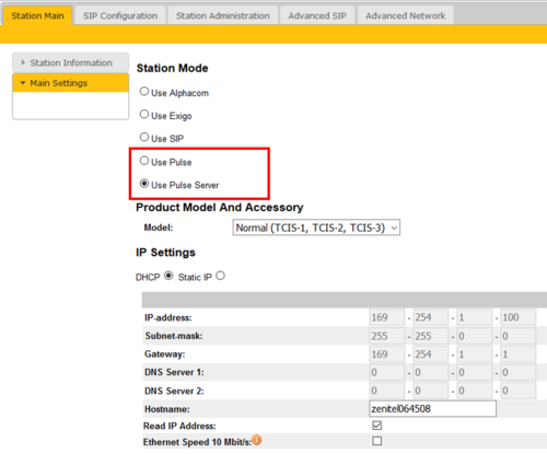
- Click Station Main > Main Settings to access the page for configuring station mode and IP parameters.
Station Mode: Select the Use Pulse Server radio-button.
- Note: Use Pulse Server must be selected to be able to carry out the configurations described in the following sections.
Product Model And Accessory: Depending on the type of Turbine hardware, there are different Product models and accessories to choose from. Find your model here: Turbine Station Models
IP Settings:
- DHCP – Select this option if the IP station shall receive IP Settings from a DHCP server.
- Static IP – Select this option if the IP station shall use a static IP address. Enter values for:
- - IP-address
- - Subnet-mask
- - Gateway
- - DNS Server 1 (option for network administration)
- - DNS Server 2 (option for network administration)
- - Hostname (option for network administration)
- Read IP Address: Check the Read IP Address box to enable an unregistered station to speak the IP address when the call button is pressed. "Read IP Address" is default enabled.
- Enable RSTP (for Industrial & Ex stations): Check the Enable RSTP box to enable RSTP. RSTP is only required when using redundant networking
- Ethernet Speed 10 Mbits/s: Default Ethernet speed is 100 Mbit/s unless switch is configured to 10 Mbit/s
Click Save followed by Apply to apply the new configuration settings.
Install License Key
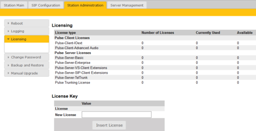
Select Station Administration > Licensing
Licenses such as Enterprise, Third Party SIP Device, Pulse Trunk, etc. can be installed here.
- Enter the license key in the New License field
- Click Insert License
Connect the remaining Intercom Stations
When the Pulse Server is configured, connect all other IP intercom stations to the network.
Note that the IP intercom stations have to be:
- In "Pulse mode". If not sure, do a Factory Default of the station. "Pulse mode" is the default mode
- On the same LAN (IP subnet) as the Pulse Server.
Wait for the stations to boot up (approximately 60 seconds) before proceeding to the next step.
Configure Server Directory
Log into the Pulse Server station with the new IP address set under Station Main > Main Settings. After login, you will find a new Server Management tab.
- Select Server Management > Server Configuration > Directory Settings
The Pulse Server station will auto-discover all the other stations on the LAN.
To identify the individual stations on the LAN:
- Click Play
- - You should now hear a tone from the station you selected.
You can now set directory numbers, names, IP addresses, profiles, etc. for all the stations in the network. In our example, the Pulse Server station is designated as Reception Desk with directory number 10 while the two substations are the Main Entrance and Rear Entrance with directory numbers 11 and 12 respectively.
- Click Save followed by Apply
- - When you click Apply, the Pulse Server will upload the directory settings to all the intercom stations and do a system reboot.
Note: Password is an optional field you can set to increase the security level. The password is used by other intercom stations to register with the Pulse Server.
Verify System Setup
To verify that your system is up and running:
- Select Server Management > Server Monitoring
All stations that have been configured should be displayed in the table. Stations that are up and running will have the status Registered.
Configure Call Buttons (DAK)
The call buttons (also called DAK keys) can be configured via the Pulse Server.
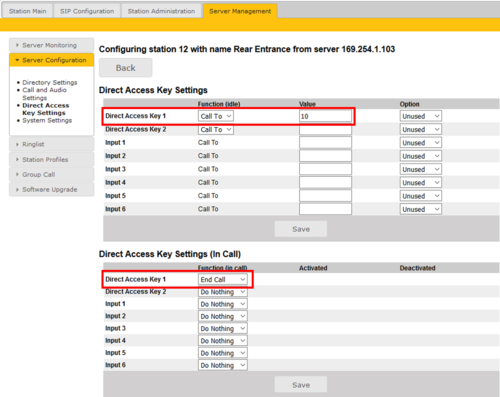
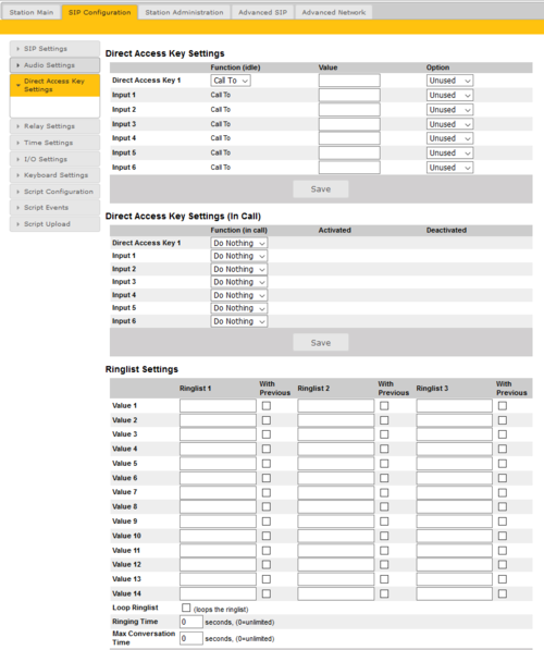
- Select Server Management > Server Configuration > Direct Access Key Settings
Direct Access Key Settings:
- Direct Access Key 1 - 10: Enter the number to call when a DAK key is pressed.
- Input 1 - 6: Enter the number to call when the input is activated.
Direct Access Key Settings (In Call):
- Direct Access Key 1 - 10: Select what action to execute if the DAK key is pressed while in a conversation.
- Input 1 - 6: Select what action to execute if the input is activated while in a conversation.
- Options are:
- End Call
- Do Nothing (Default)
- Send Text
- Send DTMF
Note: The available number of keys and inputs depend on the station type selected under Station Main > Main Settings.
Configure Call and Audio Settings
It is optional to configure the call and audio settings. Default settings will be used if they are not configured.
- Select Server Management > Server Configuration > Call and Audio Settings
The Call and Audio Settings menu include the following parameters:
- Autoanswer: When un-checked the call will be ringing (Private mode). When checked the call will connect straight through (Open mode). An optional field let you specify a delay (in seconds) before the call is auto-answered.
- Relay Configuration: Click on this link to configure the relay operation of the station
- Speaker Volume: This parameter sets the speaker volume for the station.
- Noise Reduction: This parameter enables active noise cancellation. This feature is for stations that are located in noisy environments. A level of 3 or 4 is normally suitable.
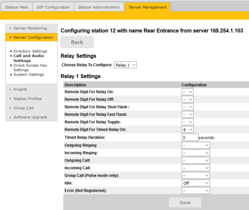
Relay Settings
To configure the relays:
- Select Server Mangement > Server Configuration > Call and Audio Settings. Select Relay Configuration for the station you want to configure.
- Relay Settings: Select Relay 1, Relay 2, Relay 3 (TA-10 Relay Unit) or Relay 4 (TA-10 Relay Unit) from the drop-downbox.
- Timed Relay Duration: This parameter determines how long the relay should stay ON in seconds when triggered by the Remote Digit For Timed Relay ON event.
Note: How many relays that are actually available depends on what station model is being used.
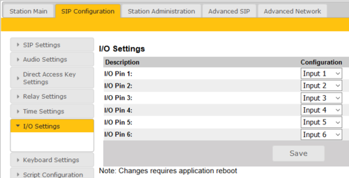
I/O Settings
The Turbine stations has 6 I/O's which can be used as an Input or an Output. By default all I/O's are set as Inputs. If you need to use an I/O as an Output, you can change the default settings.
- Select SIP Configuration > I/O Settings from the menu
- Select either Input or Output options from the drop-down box for I/O Pins 1 to 6.
Modify Station Profiles
The Station Profile defines a set of service features and parameters that are available for a group of stations.
The Pulse system can have five station profiles:
- Profile 1 - Default
- Profile 2 - Substation
- Profile 3 - Display station
- Profile 4 - Operator
- Profile 5 - Gateway
The following service features and parameters are included in the station profile:
- Door opening including remote I/O
- Outgoing call restriction
- Group Call initiation
- Busy Override
To modify station profiles:
- Select Server Management > Station Profiles
- Profile nickname: The name of the profile. Any text can be used.
- Outgoing calls allowed: Stations in selected profile can call stations in the checked profiles. «Forbidden» in the display if access is denied.
- Relay activation allowed: Stations in selected profile can activate the relay (e.g. Door Opening) on stations in the checked profiles.
- Group calls allowed: Stations in selected profile are allowed to dispatch the checked group calls
- Busy override allowed: When calling a busy station, stations in selected profile can force a connection by pressing digit 5.
Group Call
The Pulse system supports 4 group calls.
A group call is activated by dialing the appropriate code (e.g. 84). A ding-dong signal is heard in all member stations.
- Press the M-key to speak.
- Press C-key to disconnect.
- - Note 1: Group call audio can be received by STENTOFON IP stations only. Third party SIP phones cannot receive nor initiate group calls.
- - Note 2: There is no Answer function (Meet Me) for Group Calls in Pulse.
Default group call settings
The factory default settings for group calls are as follows:
| Nickname (Display text) | Directory number | Priority | Station members |
|---|---|---|---|
| All call | 84 | Emergency | All stations |
| Group call 1 | 85 | High | None |
| Group call 2 | 86 | Normal | None |
| Group call 3 | 87 | Low | None |
When adding a new station to an existing Pulse system, the new station will automatically become a member of the All call group.
Configuration of group calls
The group call properties are configured via the Pulse Server.
- Use a web browser and log into the Pulse Server station (e.g. 169.254.1.99)
- Select Server Management > Group call
- Change the parameters for each group are required:
- Nickname: This is the display text shown in the initiating station when the group call is activated. Can be any text.
- Directory number: The number to dial to activate the group call. If changed, a reboot of the Pulse Server is required for the changes to take effect.
- Priority: A group call with higher priority will override a lower priority group call.
- LOW/NORMAL: The group call audio is not played if there is an ongoing conversation
- HIGH: The group call audio is mixed with conversation audio
- EMERGENCY: Conversation audio will be muted. Includes a Volume and handset override feature. The volume is turned to maximum level on all receiving stations, and the audio comes out of the loudspeaker even if the handset is off-hook.
- Stations in group: Select the stations to be group members. You can select all stations in one operation by checking Add all stations box.
- Save: There is a Save button for each group call. Remember to press Save before you make changes to the next group call.
Troubleshooting:
Q: When making a group call, the ding-dong is heard in the stations, but no audio.
A: The problem is that the multicast audio does not reach the stations, which may be because of two things:
- If the stations are using static IP address you need to set the Gateway address for all stations.
- - Login to the Pulse Server
- - Select Station Main > Main Settings and set the Gateway address to be the Pulse Server IP Address (unless you have a real gateway).
- - Select Server Management > Server Configuration, click Save then Apply.
- - Now all stations should have a gateway address.
- The network switch may drop multicast packets (For example Linksys ”business series” switches drops all multicast packets with default configuration). If this is the problem you will need to check the manual for the network switch.
Ring List Configuration
Ringlist properties
- When using Ringlist the call will always be set up in Private Ringing mode, regardless of the Private/Open settings of the called station. Because of this property one can also use the Ringlist to force a call to be in private ringing mode, e.g. when calling from a door station.
- The Ringlist is used when the call is initiated from a call button or a Direct Access Key (DAK). The Ringlist is not in use when dialing a number on the keypad.
- The station types TCIS-6 and TCIV-6 does not support the Ringlist feature, because the call setup is using the uploaded call list, and not the Direct Access Key list.
The ringlist is configured by logging on to the web interface of the calling station, then select SIP Configuration > Direct Access Key Settings. Log on to the web interface of the station that will be making the call to configure the ringlist of the stations that should be called.
To configure a ringlist:
- Select SIP Configuration > Direct Access Key Settings
There are variants of ringlists that can be set such as ringing time intervals, loopback, and ringing together with previous stations.
Note: If you intend to include a Telephone gateway in the Ring List: Some telephone gateways accept a call immediately on incoming calls – even before the call has been accepted by the user (telephone). This terminates the ringlist sequence and any subsequent numbers in the ringlist will never be called. This is solved by placing the gateway number at the end of the ringlist and disabling the “With Previous” option. Ringlists that include an auto-accepting gateway will never loop back.
Ring List with Ringing Time Intervals
By using the Ring List, an unattended call can be forwarded to another station after a preset time. The call loop can include several stations.
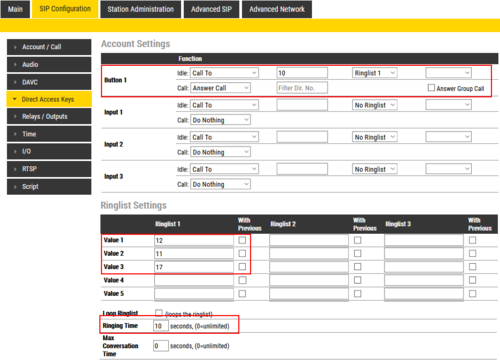
Example: When the call button is pressed, the call goes to station number 10. If not answered within 10 seconds, the call will be forwarded to station number 12. If not answered, the call will be routed to 11, and finally to station number 17.
Configuration:
Ring List with Loopback
When using the Ring List, an unattended call can be go through a call loop a preset number of times.
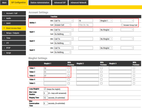
Example: When the call button is pressed, the call goes to station number 10. If not answered within 12 seconds, the call will be forwarded to station number 12. If not answered, the call will be routed to 11, and finally to station number 17.
Now the call is looped back to station number 10, repeating the same call pattern 3 times.
Configuration:
Ring List with Previous Station
By using the With Previous flag in the Ring List, one can call several stations in parallel. When one of the stations answers, it will stop ringing in the other(s).
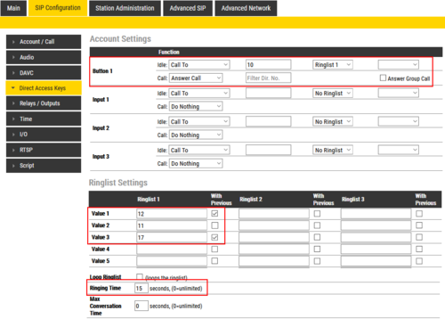
Example: When the call button is pressed, the call goes to station number 10 and 12 in parallel. If not answered within 15 seconds, the call will be forwarded to station number 11 and 17.
Configuration:
Ringlist with forwarding to external telephone
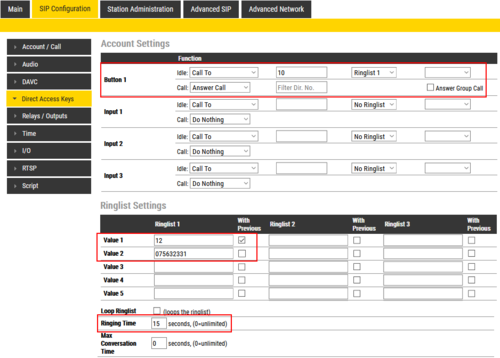
The call can be forwarded to an external telephone via a SIP Gateway. In the Ringlist, enter the prefix (e.g. "0") and the phone number in one go, e.g. "075632331".
Note: It is not possible to forward to a second telephone number if the first one doesn't answer. This because the SIP gateway will immediately "answer the call" by establishing a voice connection between it self and the Pulse server (the SIP Gateway responds with SIP 200 OK), regardless if the phone on the remote end has answered the call or not. This means that you can have only one SIP Gateway/telephone number entry in the ring list.
Function:
Configuration:
Adding SIP User Accounts for 3rd-party SIP phones
Up to 10 third party SIP phones can be registered to a Pulse system. Each phone requires that a SIP User account is defined on the Pulse Server.
Install license
Before adding SIP accounts to your system, you need to obtain the Pulse 3rd Party SIP Terminals license key.
- Log on to the Pulse Server
- Select Station Administration > Licensing.
- Enter the license key in the New License field and click Insert License
The Licensing table should now show all the licenses that are available.
Create SIP User account
- Log on to the Pulse Server.
- Select Server Management > Server Configuration > Directory Settings.
- Under Third Party SIP Terminals enter the Directory Number, Name, and Profile for the SIP telephone.
- Click Add followed by Save
The Password field can be left blank. When a password is entered, the SIP phone must register using this password.
Configure the SIP phone
You now have to log into the 3rd-party SIP telephone to configure the SIP account to register it with the Pulse Server station. The Directory Number and Password (SIP Account) created in the section above is used to register the 3rd-party station with the Pulse Server.
Adding SIP accounts for Telephone gateway
Install License
Before adding a SIP Gateway account to your system, you need to obtain the Pulse Gateway license key and install it in the Pulse Server under Station Administration > Licensing.
Create SIP Gateway Account
- Select Server Management > Server Configuration > Directory Settings
When a valid Pulse Gateway license has been installed, the Gateways parameter will be available.
- Under Gateways set the following values:
- - Directory Number: 0
- - Name: <name of your choice>
- - Profile: Default
- Click Add followed by Save
Note: Directory Number 0 is optional as you can use any number to make external calls through the Gateway
Configure the Telephone Gateway
Log into the Telephone Gateway to register it to the Pulse Server by using the SIP Gateway Account created in previous section.
Virtual I/O using Scripts
Virtual I/O is a feature for activating scripts on station events. The supported script languages are Lua and other shell scripting languages. With an I/O Extension license, the Virtual I/O feature is enabled and a station can be triggered, e.g. by DTMF to execute scripts towards other systems, e.g. access control systems. These scripts can be uploaded and configured via the menu options:
- Script Upload
- Script Configuration
- Script Events
Note: The Virtual I/O feature requires that the Pulse server must be a Turbine station with Pulse Enterprise license
Script Upload
To start with, a script should be uploaded to the station. It is possible to download scripts from the station by clicking its Name. Scripts are kept during a software upgrade process.
- Select SIP Configuration > Script Upload
- Upload Script: Click Browse to upload the desired script
Script Configuration
- Select SIP Configuration > Script Configuration
After uploading a script the user must configure a script slot (Slot 1 - Slot 10). First, assign a logical name to the script in the Assign a Label field. Then, enter the script to activate and add parameters in the text field under Enter script in selected slot (note that shell scripts don’t need to be uploaded as it is possible to write the script direclty in the text field). Lua scripts have the followings syntax:
lua <scriptname> <parameter1> <parameter2> <parameter3> ....
Shell scripts follow the same syntax, but starts with sh:
sh <scriptname> <parameter1> <parameter2> <parameter3> ...
The uploaded scripts should clearly state which parameters are needed in the beginning of the file.
The example shown in the screenshot above has 4 parameters: username, password, the IP address of the TruPortal device, and door number to activate. The parameter values in the example are:
- Username = admin
- Password = alphaadmin
- IP address = 10.5.105.202
- Door number = 4
Script Events
- Select SIP Configuration > Script Events
After a script slot has been created, you need to configure which Event that should Execute the script.
In the example below, the script "Grant Door Access" will be executed when the station receives DTMF digit #6 from the remote station:
Virtual IO Examples
Adding VS-Client Account
VS-Client is the Vingtor-Stentofon softclient intercom. Each instance of VS-Client requires a VS-Client license.
Create VS-Client Account
- Select Server Management > Server Configuration > Directory Settings
Under VS Client enter the Directory Number, Name, and Profile for the client.
- Click Add followed by Save
Adding Pulse Trunk Account
To be able to create a multi-site Pulse system, a Pulse Enterprise license and a Pulse Trunk license are required.
Install License
Install the necessary licenses under Station Administration > Licensing.
Create Pulse Trunk Account
- Select Server Management > Server Configuration > Directory Settings
- Under Pulse Trunk enter:
- - Directory Start: Directory number of first station on other Pulse system site
- - Directory End: Directory number of last station on other Pulse system site
- - (Directory numbers must be globally unique for all stations in a multi-site Pulse system.)
- - Name: Name of other Pulse system site
- - Profile: Type of station
- - Host: IP address of Pulser Server on other Pulse system site
- Click Add followed by Save
Note: The Pulse systems must be on the different subnets.
Time Settings
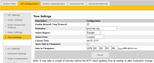
- Select SIP Configuration > Time Settings from the menu
Time Settings: You can enable Network Time Protocol, select the time zone and set the hostname or the IP address of the NTP server.

