Adding additional relay(s) to a Zenitel IP Device
From Zenitel Wiki
The Turbine Compact series has 6 I/O's which when set as outputs can be used together with the conventional Multi Relay Board (MRBD) to give up to 6 additional Normal Open or Closed contacts.
All 6 relays on the MRBD are double pole, double throw (DPDT) contacts.
Contents
Requirements
- Hardware: The Turbine station must be produced week 37 of 2012 or later.
- Software: The Turbine Station must have sw version TCIS-3.0.3.3 or newer.
MRBD Configuration
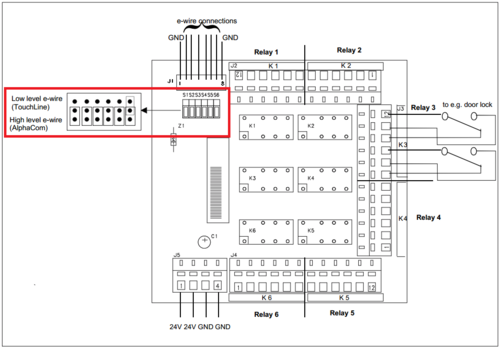
The MRBD has 6 jumpers (S1-S6) which allows to set the relays individually to be used with AlphaCom system (active "high" signal) or the older TouchLine system (active "low" signal). Default the MRBD comes with the jumpers set for AlphaCom mode.
When a relay is used with Turbine, the associated jumper must be set to "TouchLine"
See MRBD - Relay Board for more details on the Multi Relay Board.
Connection
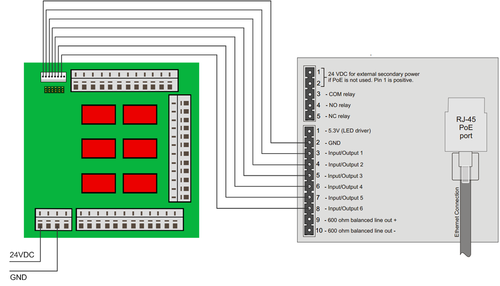
The MRBD need 24VDC to operate. This power can be retrieved from AlphaCom Audio Servers XE7, XE20 and XE26 (the latter with additional PDB).
- Connect the 0V from the Turbine Compact to the GND on the MRBD
- Connect the I/O('s) from the Turbine Compact to the Input(s) on the MRBD
See TCIS Connections for more details on Turbine Compact connections.
Turbine Web configuration
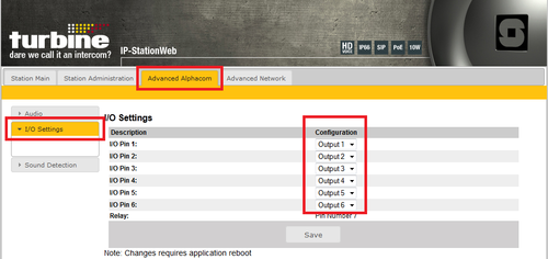
The Turbine station must be configured to register to the AlphaCom in the standard way. In addition the I/O's used with the MRBD must be set to Outputs.
Log on to the Turbine station and navigate to Advanced AlphaCom -> I/O Settings.
Set the I/O('s) that are connected to the MRBD as Output.
See TCIS Configuration for more details on configuring the Turbine Compact.
AlphaPro configuration
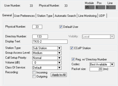
The Turbine Compact station (or TKIS-2 Kit) must be defined in AlphaPro as a CCoIP station.
RCO mapping
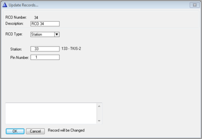
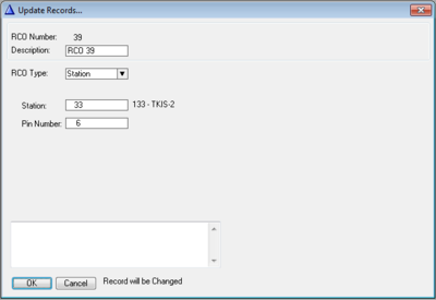
The outputs of the Turbine station must be mapped to logical RCO's in the AlphaCom. In Exchange & System -> RCO select a free RCO and press change.
- RCO Type: Change to Station.
- Station field: Enter the physical number of the Turbine Compact
- Pin Number field: Enter the output (1-6) to be controlled by that logical RCO
Events
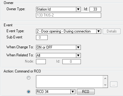
The RCO's are controlled using the Event Handler. Here are three practical examples:
- 1: Controling the door lock
- RCO 34 controls output 1 on the Turbine Compact. When this event is triggered relay 1 on the MRBD is activated for 3.5 seconds.
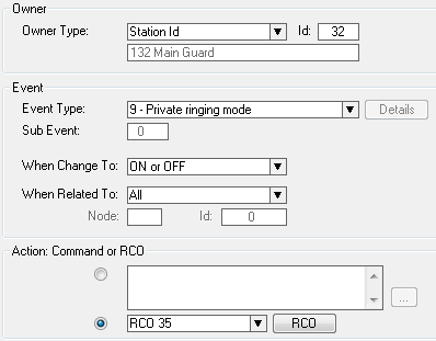
- 2: Activating a rotating lamp on incoming call
- This event triggers when someone is calling the Main Guard which is in Private Mode. It will activate RCO 35, which is physically output 2 on the TKIS-2 with physical number 33. This output controls relay 2 on the MRBD which when activated turns on a rotating lamp to alert the Main Guard that there is an incoming call.
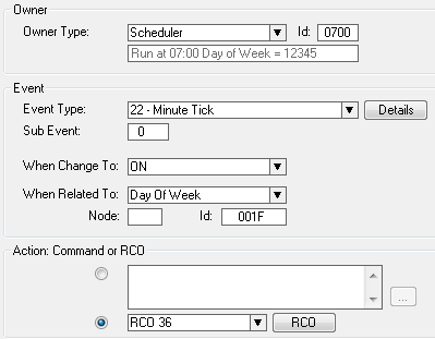
- 3: Opening a barrier at a predefined time
- This event will trigger at 7am from Monday to Friday. It will activate RCO 36 which is output number 3 on the TKIS. This in turn operates relay 3 on the MRBD, and the barrier is raised.
Upload Data
When AlphaPro configuration is finished, upload the data by pressing Send All or Send Change from the top menu. After the upload is complete reset the exchange to make the changes take effect.

