
System Configuration Tool - SCT
From Zenitel Wiki

The PAVA System Configuration Tool (SCT) is the Zenitel desktop application used to configure a VIPEDIA PA/VA System. The screenshot is from SCT v5.1.4.2P with an example training configuration loaded; each highlighted area of the image links to the matching section further down this page.
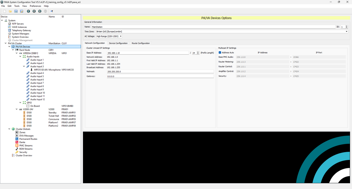
Interface Areas
| Area | Purpose |
| Title Bar | Shows the tool name, version, and the file name of the configuration currently open |
| Menu Bar | File, Edit, Tools, View, Preferences and Help menus |
| Toolbar | Quick-access icons for the most common File-menu and device-communication actions, including R - RDT (Router Dynamic Tool) / A - ADT (Amplifier Dynamic Tool) / F - FTT (File Transfer Tool) |
| System Device Treeview | Navigation tree listing physical devices configured on the project, under the System and PA/VA Cluster branches |
| PA/VA General Information | Identity and mains-power settings for the selected device: Name, ID, Time Zone, AC Voltage |
| Configuration Tabs | Switches between Network Configuration, Device Configuration and Route Configuration views |
| Cluster Unicast IP Settings | Base IP addressing for the cluster: Base IP Address, Prefix Length, Netmask, Gateway |
| Multicast IP Settings | Multicast group addresses and UDP ports used for control and audio traffic |
Title Bar
The application title bar shows the tool name and version (PAVA System Configuration Tool V5.1.4.2P) together with the file name of the configuration currently open — in this example, v5_training_config_v5.1.42P.pava_sct.
Menu Bar
The standard menu bar:
- File – New/Open/Save/Import/Export configurations
- Edit - Add / Delete items
- Tools - Start tools / reassign configuration parameters
- View - Dynamic Allocation Table (DAT) usage filters
- Preferences – application-level settings
- Help - About / Tooltips
Toolbar
Quick-access icons beneath the menu bar, mirroring the most common File-menu actions (new, open, save, save-as) plus a set of connection/device-communication icons and a Treeview toggle (the "T" icon).
Hover over each icon in the live tool for its exact tooltip, as labelling can vary slightly between SCT releases.
System Device Treeview
The left-hand navigation tree lists every device in the project, organised under two top-level branches:
- System – global, cluster-independent settings: NTP Servers, VAVE Instances, Telephony Gateway, System Managers, System Overview and Cluster Management.
- PA/VA Cluster – the cluster itself (here named MainStation, cluster ID
CLU1), expanded down to:- A Rack Node (
CER1) containing a VIPEDIA unit (deviceDBB1, IDVIP01) with:- 12 Audio Inputs, one of which (Audio Input 3) has an MPS10 G0 AN microphone attached (tag
VIP01:MIC03) - A GPIO block ("On Board", tag
VIP01:BMB0) - A V2000-24V amplifier frame (
FRM01) carrying five D500 amplifier channels, mapped to the zones Standby, Ticket Hall, Concourse, Platform 1 and Platform 2
- 12 Audio Inputs, one of which (Audio Input 3) has an MPS10 G0 AN microphone attached (tag
- Cluster Globals – settings shared across the whole cluster: Zones, DVA Messages, Permanent Routes, Dante, PMC Streams, BGM Streams, Security and Cluster Overview.
- A Rack Node (
Selecting any node in this tree changes the content shown in the right-hand panel described below.
Configuration Pane
The Configuration Pane is where all detailed configuration editing is completed. It driven by the selection in the System Device Tree as to which device is being configured. This is defined by the yellow banner at the top of the panel which names the type of device currently selected — here, PA/VA Devices Options for the highlighted "PA/VA Devices" node and comprises the following sections;

|
If this panel renders blank, check that a device is selected in the System Device Tree. |
General Information
- Identity and mains-power settings for the selected device:
- Name –
MainStation - ID –
1 - Time Zone –
Britain (UK) [Europe/London] - AC Voltage –
High Range (220–250V)**This is a mandatory setting and configuration save is unavailable until set.
- Name –
Configuration Tabs
- Three tabs switch the lower part of the right-hand panel between views for the selected device: Network Configuration (shown here), Device Configuration and Route Configuration.
Cluster Unicast IP Settings
- Defines the cluster's base IP addressing.
- Base IP Address (
192.168.1.10) and Prefix Length (/24) are entered directly - Network Address, First/Last Valid IP Address and Broadcast Address are derived automatically from those two values
- Netmask (
255.255.255.0) and Gateway (0.0.0.0) remain independently editable
- Base IP Address (
Multicast IP Settings
- The multicast group addresses and UDP ports the cluster uses for control and audio traffic, each derived from the Base IP Address when Address Auto is ticked:
Stream Multicast Address Port Base PMC Audio 239.1.0.0 15366 Router Metering 239.1.0.3 17422 Router Control 239.1.0.1 17423 Amplifier Control 239.1.0.2 17424 Security 239.1.0.4 17425
Related Pages