Difference between revisions of "ICX Web"
From Zenitel Wiki
(→User Management) |
(→User Management) |
||
| Line 374: | Line 374: | ||
* Read/Write User: admin/alphaadmin | * Read/Write User: admin/alphaadmin | ||
* Custom Script User: scripter/alphascript | * Custom Script User: scripter/alphascript | ||
| + | |||
| + | <br> | ||
===Time and Date=== | ===Time and Date=== | ||
Revision as of 08:18, 8 July 2019
This article describes the web interface of the ICX-500 Gateway.
The ICX-500 gateway runs an embedded web server. It allows the users to log in using a standard web browser such as Chrome or Firefox to operate and manage the ICX-500 system. The web server provides functions for system monitoring, configuration, and software upgrade.
Contents
- 1 Initial connection
- 2 System Monitoring
- 3 System Configuration
- 4 System Maintenance
- 5 Help
- 6 Backup and Restore
Initial connection
Logging in
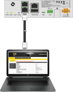
Initial connection is done by connecting a laptop to Eth port 0, open a web browser (e.g. Firefox or Chrome), and type in the IP address in the address field of the browser:
- Default IP address 169.254.1.5
- Default Username: admin
- Default Password: alphaadmin
These credentials will give Read/Write privileges, making it possible to do changes in the configuration.
To log in with Read privileges only, the credentials are:
- Default Username: alpha
- Default Password: com
With these credentials one can check status and read information, but not make any changes to the system.
Changing Default User Name and Password
For security reasons it is recommended to change the default user names and passwords.
- Select System Configuration > User Management
- Enter the Current Password for both Read access and Read/Write access (default: com and alphaadmin)
- Enter new User Name and Password
- Re-enter the New Passwords to confirm
- Verify by clicking Update User 1 and Update User 2
- Write down the selected passwords and keep them in a secure place.
Saving and Applying changes
When new configuration parameters are entered, they are saved to the configuration file by clicking Save. To apply the new settings to the running configuration, click Apply.
System Monitoring
Node Information
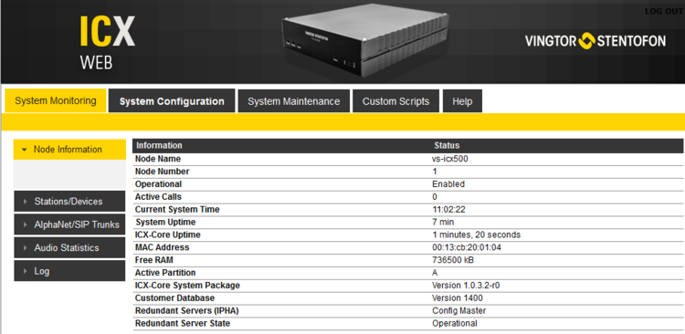
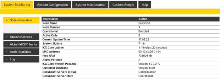
Shows general information about the system such as Node Name and Node Number. It also shows state information; different times and memory usage. Information about the Software Configuration, and the Hardware Configuration (the different boards and versions), and also the state of the different processes running in the system.
- Node name: The name of the gateway, as configured from AlphaPro, Exchange & System > System menu.
- Node number: Default node number is 1. The node number is used for communication between gateways interconnected in a network (AlphaNet). The node number can be changed from AlphaPro, Exchange & System > System menu.
- Operational: Enabled: The intercom application (vs-amcd) is running. Disabled: The intercom application is not running.
- Active Calls: Shows the number of currently active calls. Refresh (F5) the web page to see current status. If there is a need to restart the system, one can wait until there are no active calls in the system.
- Current System Time: Shows the current time in the ICX-500, as presented in display stations.
- System Uptime: The time elapsed since last time the system (Linux) started
- ICXCORE Uptime: The time elapsed since last time the intercom application (vs-amcd) started
- MAC Address: Shows the MAC address of the ICX-500.
- Total Space (FLASH / DATA FLASH / RAMS): Total memory space.
- FLASH: Memory space for program files, such as Linux and all program modules (vs-amcd, vs-sipd, vs-alphaweb etc.)
- DATA FLASH: Memory space for storing of data, such as log files, voice messages and billing data (Not program files)
- RAMFS: RAM File System for storing of temporary data, such as package uploads, web work files, Billing configuration and various status data.
- Free Space (FLASH / DATA FLASH / RAMS): Available space in Flash memory.
- Free RAM: Available space in RAM memory.
- Active Partition: Show which of the two partitions A or B that is currently active.
- ICXCORE System Package: Show the version of the software package running on the partition that is currently active.
- Customer Database: The version of the customer database
Services
In the "Services" section one can see which software services are currently running, and their version number.
Stations/Devices
Configured
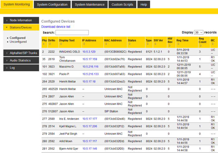
The table can be sorted by clicking on the relevant header. In the Search field you can search for any free text, e.g. directory number, display text or IP address. Click on Download device list to open the station list in Excel spreedsheet.
- Physical Numbers: The physical number is the index number to which the station or device is assosiated.
- Directory Number: The directory number is the number you must dial to reach the station.
- Display Text: The caller ID of the station as programmed in AlphaPro, Users & Stations.
- IP Address: The IP address of the IP Station or SIP Station. Clicking on the IP address will open a new tab in your browser and connect to that IP address.
- MAC Address: Shows the MAC address of IP stations.
- (0013cb00c7e9): When the MAC address is displayed in brackets, the station is "Registered with Directory Number". The MAC address will only show when the station is registered, else it will show DIP free MAC.
- 0013CB00C7E9: When the MAC address is displayed without brackets, the station is configured in AlphaPro to "Register with its MAC address". The MAC address will show regardless if the station is registered or not.
- DIP free MAC: The IP station is configured in AlphaPro to "Register with Directory Number", but is not registered.
- SIP Station: The station is configured as a "SIP Station" in AlphaPro.
- Status : Shows the registration status of the station
- Not Registered: The IP station or SIP station is configured in the ICX, but has not been able to register.
- Registered: The IP station or SIP station has successfully registered to the ICX.
- No License: The registration was rejected due to missing license.
- Type: Shows what type of equipment which is connected/registered.
- 8020 - Dual Display Station
- 8022 - INCA IP Sub Station
- 8023 - Flush Master Station
- 8024 - Desk Master Station
- 8026 - IP ARIO
- 8121 - Turbine Compact
- 8124 - Turbine Extended
- 8511 - TFIX station
- 100 - SIP Phone/Station
- 101 - IP Dummy Station
- SW Ver: Shows the software version on the IP station.
- HW Rev: Shows the IP station hardware version.
- Reg Time: Registration Time. Shows the last time the station got registered to the ICX.
- Reg Count: Registration Counter. Shows the number of registerations to the ICX-500 gateway. The counter will be cleared when the ICX is reset.
- MC: MultiCast. Status information about Group Audio configuration (Groupcall, Audio Program, Simplex Conference) and status of the IP station.
- UC: Unicast
- M0 or M1: Direct multicast on ethernet ports 0 or 1
- R0 to R4: Relayed multicast to Group 0 to 4
- See Multicast for more details.
Unconfigured
The "Unconfigured" list shows stations that are able to connect to the ICX-500 gateway, but not able to register.
Typical reasons for not being able to register are:
- The directory number specified in the station web does not exist in the ICX-500 gateway
- The "CCoIP Station" flag is not enabled
Check "Directory Number" and "CCoIP Station" flag settings in AlphaPro, Users & Stations.
AlphaNet
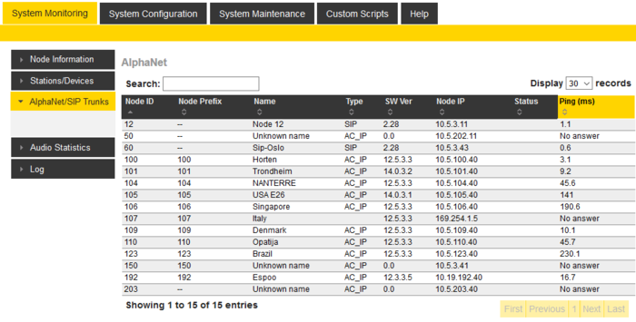
This table shows all AlphaNet and SIP Trunk connections.
The table shows:
- Node ID: Unique index number (1 - 254) of the ICX node or the SIP Trunk node
- Node Prefix: The prefix to dial on the intercom station to reach that node
- Name: Shows the name of the node. If the name is changed from AlphaPro, a small reset is required for the name to be updated.
- Type:
- AC_IP: AlphaCom or ICX node.
- SIP: SIP Trunk node.
- SW Ver: Software Version of the node
- Node IP: The IP Address of the node
- Status: Shows the communication status to the remote node
- Up: The communication with the node is OK
- Down: Communication error with the node
- Ping Test: Check if this node can do a ping request to the remote nodes. If Ping is OK, the ping time for each node will appear in the list
See also AlphaNet Troubleshooting
Audio Statistics
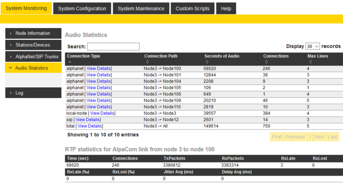
The ICX-500 collects Audio Statistics and RTP Statistics for local calls as well as for AlphaNet and SIP Trunk calls. The statistics are cleared when the ICX-500 is reset.
Audio Statistics:
- Connection Type: Local calls inside this node, AlphaNet calls or SIP Trunk calls.
- Connection Path: Shows between which nodes the statistics are for
- Seconds of Audio: The total time of audio for all conversations
- Connections: The number of connections since last reset
- Max Lines: The peak of concurrent calls
RTP Statistics:
Click on View Details on one of the connections to see detailed RTP statistics for that connection:
- Time (sec): Total duration of connections
- Connections: Number of connections
- TxPacktes: Count of RTP packets transmitted
- RxPacktes: Count of RTP packets received in time playout
- RxLate: Count of RTP packets received too late for playout
- RxLost: Count of RTP packets not received at all
- RxLost (‰): (RxLate / RxPacktes) * 1000
- RxLost (‰): (RxLost / RxPacktes) * 1000
The "Jitter Avg" and "Delay Avg" are average values of the last 10 connections:
- Jitter Avg (ms): Jitter computed as in A.8 of RFC3550, sampled once every second, and converted to milliseconds.
- Delay Avg (ms): Localt Rx jitter buffer delay, sampled once every second, and converted to milliseconds.
Logs
Log files stored on the ICX-500 gateway can be viewed or downloaded by selecting System Monitoring > Logging.
- To view a log file directly in the browser, Select Log to read, then press Submit.
- To download the log file, press the link under Filename, and store the log file on the laptop

|
By default logging is disabled. To enable logging, select System Configuration > Logging |
System Configuration
Interfaces
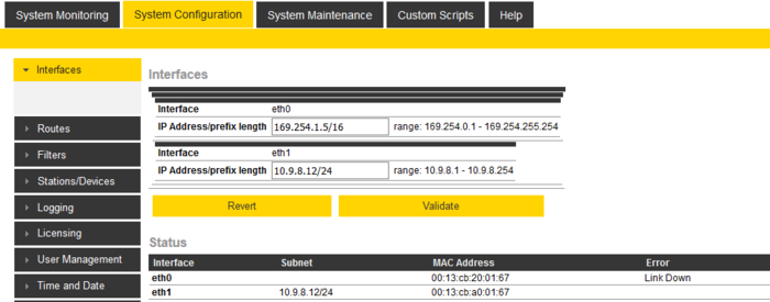
There are two Ethernet interfaces on the ICX-500 Gateway, Eth0 and Eth1. The IP address is set by using CIDR notation. It appends a slash character ("/") to the address and a decimal number specifying the number of bits (out of the total 32 bits of an IP address) that the network prefix consists of.
Factory Default settings are:
- Eth0: 169.254.1.5/16
- Eth1: 0.0.0.0/32 (obtain IP Address automatically - DHCP)
Enter the IP address, press Validate, and then Save & Apply.
Examples of CIDR notation and equivalent dot-decimal notation:
- 169.254.1.5/16 is equivalent to IP address 169.254.1.5 and net mask 255.255.0.0.
- 10.5.101.30/24 is equivalent to IP address 10.5.101.30 and net mask 255.255.255.0.
- 192.168.1.40/26 is equivalent to IP address 192.168.1.40 and net mask 255.255.255.192.
See here for more examples.
Routes
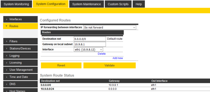
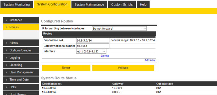
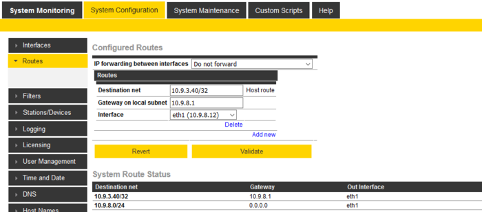
The Routing table must be configured if there is a need to communicate with devices outside own subnet. Three different route types can be defined:
- Default route (= Default gateway)
- Net route - A route to one particular IP network
- Host route - A route to one particular host
Defining a Default Gateway
To define a Default Gateway, select Add New, and enter:
- Destination net = 0.0.0.0/0
- Gateway on local subnet = IP Address of the default gateway
- Interface = On which Ethernet interface the default gateway is located
- Press Validate
- Press Save & Apply
Defining a Net Route
To define a route to one particular network, select Add New, and enter:
- Destination net = IP address of the remote IP network in CIDR notation
- Gateway on local subnet = IP Address of the gateway
- Interface = On which Ethernet interface the gateway is located
- Press Validate
- Press Save & Apply
Defining a Host Route
To define a Host route, select Add New, and enter:
- Destination net = <IP address of the host>/32
- Gateway on local subnet = IP Address of the gateway
- Interface = On which Ethernet interface the gateway is located
- Press Validate
- Press Save & Apply
Filters
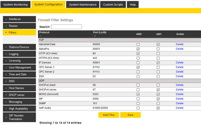
The built-in firewall of the ICX-500 Gateway is by default configured for management services (AlphaPro, Web Interface) on Ethernet port 0, and VoIP services (e.g. IP- and SIP stations, AlphaNet) on ethernet port 1.
In the Filters Settings one can modify what services should be available on each ethernet interface.
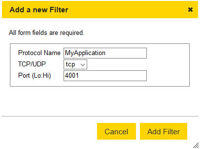
New TCP or UDP ports can be added by selecting Add Filter. Remember to enable it after adding!
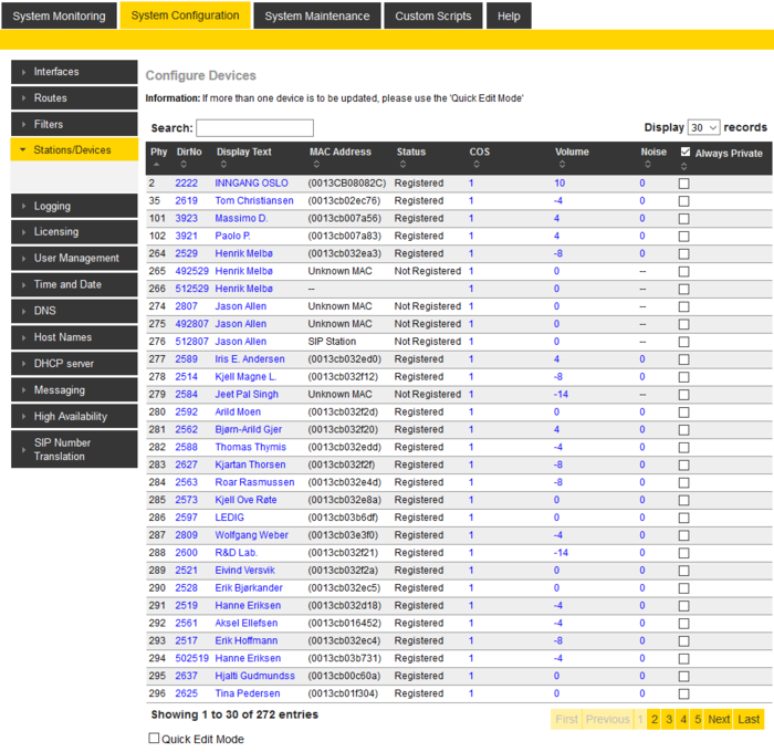
Stations/Devices.
From the Stations/Devices list some user parameters can be modified.
The table can be sorted by clicking on the relevant header. In the Search field you can search for any free text, e.g. directory number, display text or IP address.
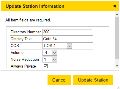
By clicking on a station in the list, the following parameters can be modified:
- Directory Number
- Display Text
- COS (Class of service)
- Volume
- Noise Reduction
- Always Private
Changes will take immediate effect. No reset is required.
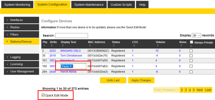
Quick Edit Mode
When multiple changes are to be made, the Quick Edit Mode can be enabled, and each parameter can be modified directly from the table without having to open an extra window.
Remember to click on Apply Changes to save the changes.
Logging
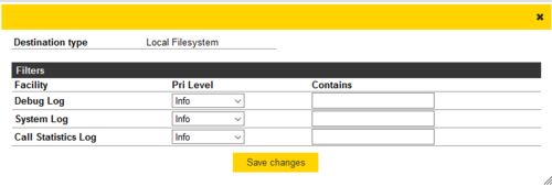
There are three different log types:
- Debug Log: Low level messages. For debugging purposes for software engineers.
- System Log: Provides log events for monitoring the health of the ICX system. The log includes Station Line errors, restart, backup/restore, Customized event logging (LOG command) etc.
- Call Statistics Log: Detailed information about Calls, Call Requests, Group calls, external SIP trunk calls
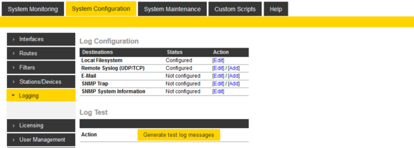
There are four different log Destinations:
- Local Filesystem - Log files are stored locally on the ICX-500 Gateway. Logs can be viewed or downloaded from System Monitoring > Logs
- Remote SysLog - Enter the IP Address of the remote computer, and the protocol type (UDP or TCP)
- E-Mail - If the ICX-500 has access to an e-mail server, log events can be forwarded to a predefined e-mail address
- SNMP Trap - Enter the IP Address of the remote computer running the SNMP service. Select SNMP System Information to configure additional SNMP parameters (Name, Location, Contact, Community String and SNMP Port).
To configure logging press Edit next to the Destination, and enter relevant parameters. The different logs are enabled by setting "Pri Level" = Info.
After changed are Saved and Applied, the logging can be tested by clicking on "Generate test log messages".
To filter on a specific text in the log strings, add the required text in the Contains field. Only log events that contain this text will be sent to the log.
Logging to Local Filesystem
The log system is creating a new file every day for each of the log types (Debug, System and Statistics).
Log rotation is used to prevent the logs from growing out of control. Every 10 minutes there is a check if the log files are consuming more than 3MB of memory space. If more than 3MB, the oldest log file will be deleted, until the remaining space is below 3MB. I.e. you will loose one day of logging each time a log file is deleted.
Clean up will remove 10% of the oldest log content. Delete will delete the complete log file.
Licensing
For how to obtain and install licenses, see Licenses for ICX-500 and ICX-Core.
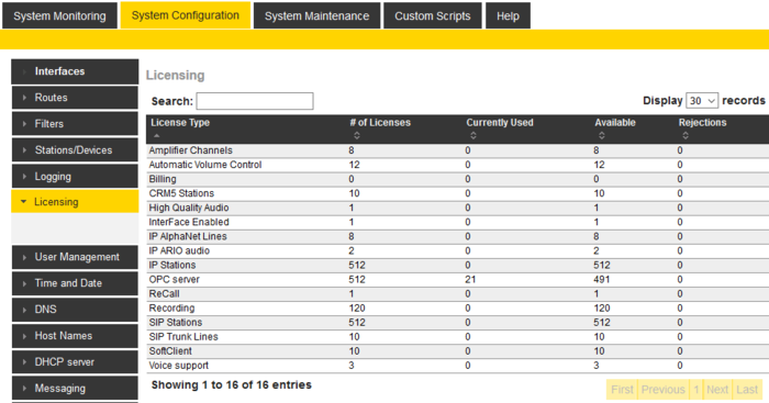
Installed licenses are displayed in System Configuration > Licensing.
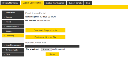
The ICX system comes with a 20-day free license period. Until valid licenses are installed, the remaining time of the free period is displayed.
User Management
It is highly recommended to change username and password. This is done in System configuration/User management
Default username/password:
- Read User: alpha/com
- Read/Write User: admin/alphaadmin
- Custom Script User: scripter/alphascript
Time and Date
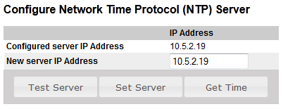
The real-time clock in AlphaCom can be synchronised to a Network Time Protocol (NTP) server. This is set up in System configuration -> Time manager.
The button "Get Time" will read the NTP time and set the AMC realtime clock.
The clock is automatically syncronized once an hour (20 minutes past the hour).
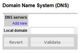
DNS
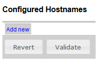
Hostnames
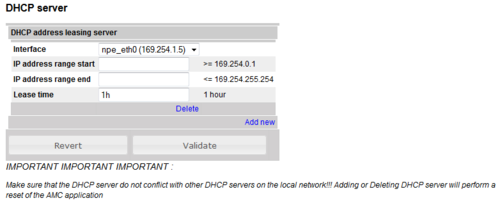
DHCP server
Messaging
Only for black (AMC11) AMC-IP boards.
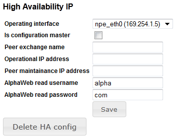
High Availability
Only for black (AMC11) AMC-IP boards.
System Maintenance
System Upgrade
AMC software is upgraded in System upgrade.
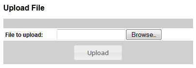
Browse for the new software and do an upload to AMC-IP.
Then do a ”Select” and ”Install Selected”
For details se AMC-IP software upgrade
See also AlphaCom E Software packages
IP Station Upgrade
IP Station Discovery:
To search for IP Stations in the range 10.5.101.100 to 10.5.101.200, enter:
- Class C Network: 10.5.101
- Subnet Start: 100
- Subnet End: 200
A list of stations will appear when the search is finnished. By clicking on the IP address in the list you will be connected to the web server of that station.
Config Backup
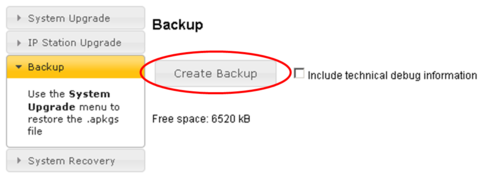
This is performed in System Maintenance/Backup
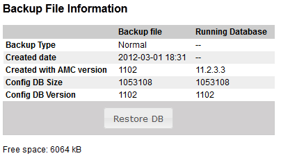
The "Create Backup" button will update the backup.bin in AMC.
You will simultaneously be asked if you want to store the file to your PC/server. This will be an .apkg file containing both IP setteings and the Database.
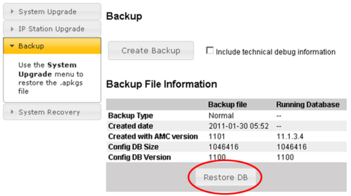
The "Restore DB" button is used to restore the Database from the onboard memory.
See also: Backup
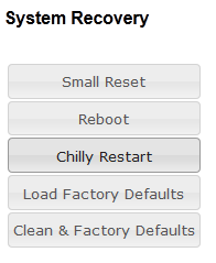
System Recovery
- Small Reset: Reset main applications
- Reboot: Reboots the system
- Chilly Restart: Reset main applications and clear state data like mails, transfers, absense, %udd and program selection. Configuration data are kept.
- Load Factory Default: Reset intercom configuration data. IP settings are kept.
- Clean & Factory Defaults: Reset intercom configuration data. Remove License, SysLog and Backup files. IP settings are kept.
Help
Backup and Restore
Create Backup
Navigate to System Maintenance -> Backup and click Create Backup.
An AlphaPro backup file will be stored in the on-board flash memory (same as dialling 7820). You will be prompted to store a full backupfile (AlphaPro and AlphaWeb settings) on your computer.
Store configuration to AMC Flash Memory from station: 7820 + M
Restore configuration from AMC Flash Memory from station: 7819 + M
Restore Backup from AMC
The AlphaPro configuration can be restored from the AMC-IP onboard memory by dialling 7819 + M on a superuser station. It can also be restored in AlphaWeb:
Navigate to System Maintenance -> Backup and click Restore DB.
Restore full Backup from PC
The full backup containing both AlphaPro and AlphaWeb settings must be uploaded, installed and activated in AlphaWeb.
Navigate to System Maintenance -> System Upgrade and click Browse. Browse your computer for the correct backup file and select Upload.
Two files will now appear:
- Select the first file. Click the Install button that becomes available.
- After the installation is done, repeat for the second file.
- Navigate to System Mainteneance -> Backup and click Restore DB. This will restore the AlphaPro database.
- Navigate to System Configuration -> Interfaces and press Save followed by Apply and confirm with Yes. This will activate all the AlphaWeb settings.
- Navigate to System Maintenance -> System Recovery and click Reboot. Reboots the system to make all changes take full effect.


