IP SubStation with Video and Inductive Loop: Difference between revisions
From Zenitel Wiki
| (20 intermediate revisions by 3 users not shown) | |||
| Line 1: | Line 1: | ||
[[File:IP Substation with Video and Inductive Loop.png|thumb| | {{obsolete}} | ||
[[File:IP Substation with Video and Inductive Loop.png|thumb|200px|IP Substation with Video and Inductive Loop]] | |||
Designed to meet the needs of a building management system, the IP video and audio solution works without video server and meets the Handicap standards. This unit blends in perfectly with the STENTOFON IP system and will therefore integrate with most security systems. The IP Intercom Station is equipped with an inductive loop for deaf persons and a back-lit and embossed call button for visually impaired people. | Designed to meet the needs of a building management system, the IP video and audio solution works without video server and meets the Handicap standards. This unit blends in perfectly with the STENTOFON IP system and will therefore integrate with most security systems. The IP Intercom Station is equipped with an inductive loop for deaf persons and a back-lit and embossed call button for visually impaired people. | ||
| Line 7: | Line 8: | ||
=Configuration= | =Configuration= | ||
For camera configuration see [[ | For camera configuration see [[IP_Desktop_Master_Station_with_Video_Display_-_Configuration_Guide#IP_Video_Substation_1038051415|IP Video Substation]] | ||
==IP and Server settings== | ==IP and Server settings== | ||
The station must be given an IP address, either static or one provided by a DHCP server. In addition the IP address of the AlphaCom and the directory number must be set. This is all done in the inbuilt webserver. | The station must be given an IP address, either static or one provided by a DHCP server. In addition the IP address of the AlphaCom and the directory number must be set. This is all done in the inbuilt webserver. | ||
For more details, please see: [[ | For more details, please see: [[IP_Station_Configuration#Station_Main_Settings|IP Station IP and Server configuration]] | ||
<br style="clear:both;" /> | <br style="clear:both;" /> | ||
| Line 38: | Line 39: | ||
The "bell" LED is used to indicate that the station is in ringing mode. This mode can be achieved in two ways: | The "bell" LED is used to indicate that the station is in ringing mode. This mode can be achieved in two ways: | ||
:1: The ''called'' station is in private | :1: The ''called'' station is in private | ||
:2: The IP SubStation makes a [[Call Request]] to another station, thus putting the IP SubStation in | :2: The IP SubStation makes a [[Call Request]] to another station, thus putting the IP SubStation in Call Requester Mode | ||
Depending on the two variants, one of these two following event can be used: | Depending on the two variants, one of these two following event can be used: | ||
| Line 50: | Line 51: | ||
|width="400pt"|Stations w. UDP, Id: 2 (Stations w/monitor) | |width="400pt"|Stations w. UDP, Id: 2 (Stations w/monitor) | ||
|- | |- | ||
|'''Event type''': || [[Private Ringing | |'''Event type''': || [[Private Ringing mode (Event Type)|9 – Private Ringing Mode]] | ||
|- | |- | ||
|'''Subevent''': || n/a | |'''Subevent''': || n/a | ||
| Line 67: | Line 68: | ||
IND %2.phy 1 2 1 commands station %2.phy (which is equal to the physical number of the related to station) to turn on (or off, depending on the "When Change To" state) the amber LED to the "bell" | IND %2.phy 1 2 1 commands station %2.phy (which is equal to the physical number of the related to station) to turn on (or off, depending on the "When Change To" state) the amber LED to the "bell" | ||
<br style="clear:both;" /> | |||
------------ | ------------ | ||
| Line 77: | Line 78: | ||
|width="400pt"|Stations w. UDP, Id: 1 (Stations w/cam) | |width="400pt"|Stations w. UDP, Id: 1 (Stations w/cam) | ||
|- | |- | ||
|'''Event type''': || [[Call | |'''Event type''': || [[Call Requester Mode (Event Type)|11 – Call Requester Mode]] | ||
|- | |- | ||
|'''Subevent''': || n/a | |'''Subevent''': || n/a | ||
| Line 94: | Line 95: | ||
IND %1.phy 1 2 1 commands station %1.phy (which is equal to the physical number of the owner of the event) to turn on (or off, depending on the "When Change To" state) the amber LED to the "bell" | IND %1.phy 1 2 1 commands station %1.phy (which is equal to the physical number of the owner of the event) to turn on (or off, depending on the "When Change To" state) the amber LED to the "bell" | ||
<br style="clear:both;" /> | |||
===The "head" LED=== | ===The "head" LED=== | ||
| Line 127: | Line 129: | ||
IND %1.phy 1 1 1 commands station %1.phy (which is equal to the physical number of the owner station) to turn on (or off, depending on the "When Change To" state) the amber LED to the "head" | IND %1.phy 1 1 1 commands station %1.phy (which is equal to the physical number of the owner station) to turn on (or off, depending on the "When Change To" state) the amber LED to the "head" | ||
<br style="clear:both;" /> | |||
------------ | ------------ | ||
| Line 154: | Line 156: | ||
IND %1.phy 1 1 1 commands station %1.phy (which is equal to the physical number of the owner of the event) to turn on (or off, depending on the "When Change To" state) the amber LED to the "head" | IND %1.phy 1 1 1 commands station %1.phy (which is equal to the physical number of the owner of the event) to turn on (or off, depending on the "When Change To" state) the amber LED to the "head" | ||
<br style="clear:both;" /> | |||
===The "door" LED=== | ===The "door" LED=== | ||
| Line 166: | Line 169: | ||
|width="400pt"|Stations Id, Id: 34 (134 Door Station) | |width="400pt"|Stations Id, Id: 34 (134 Door Station) | ||
|- | |- | ||
|'''Event type''': || [[Door Opening - During | |'''Event type''': || [[Door Opening - During Conversation (Event Type)|2 – Door Opening - During Conversation]] | ||
|- | |- | ||
|'''Subevent''': || n/a | |'''Subevent''': || n/a | ||
| Line 183: | Line 186: | ||
Explanation: | Explanation: | ||
The event will trigger when 6 is dialed during conversation by the remote party. The event will turn on the RCO equal to the physical number of the event owner (the IP SubStation) for 3.5 seconds. In addition it will activate the green "door" LED for the duration of the event (default 3.5 seconds). | The event will trigger when 6 is dialed during conversation by the remote party. The event will turn on the RCO equal to the physical number of the event owner (the IP SubStation) for 3.5 seconds. In addition it will activate the green "door" LED for the duration of the event (default 3.5 seconds). | ||
<br style="clear:both;" /> | |||
=Related Articles= | |||
*[[IP Desktop Master Station with Video Display - Configuration Guide]] | |||
* [[:Category:INCA Release notes|Software Release Notes]] | |||
[[Category: Discontinued Stations]] | |||
Latest revision as of 11:52, 23 June 2022
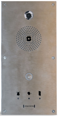
Designed to meet the needs of a building management system, the IP video and audio solution works without video server and meets the Handicap standards. This unit blends in perfectly with the STENTOFON IP system and will therefore integrate with most security systems. The IP Intercom Station is equipped with an inductive loop for deaf persons and a back-lit and embossed call button for visually impaired people.
The video and audio IP Intercom unit is the only station in the market that offers VoIP audio, IP video and an Inductive Loop in one box! As it has onboard video there is no need to integrate it with an IP CCTV network and there is no additional cost for licenses (not needed). The HD audio quality, the ability to have an unlimited number of stations and the ease of installation allow this product to integrate effortlessly with public buildings.
Configuration
For camera configuration see IP Video Substation
IP and Server settings
The station must be given an IP address, either static or one provided by a DHCP server. In addition the IP address of the AlphaCom and the directory number must be set. This is all done in the inbuilt webserver.
For more details, please see: IP Station IP and Server configuration
Call button
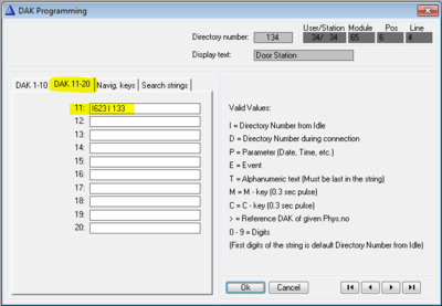
Normally an IP Substation uses DAK 1 as the call button. In the IP SubStation with Video and Inductive Loop the call button is DAK 11. To configure DAK 11 use AlphaPro and select the user you want to configure. Give the IP SubStation a name and Directory number as per you requirement. Proceed to click the DAK button in the lower left corner.
A new window appear. Select the DAK 11-20 tab, and put in the call number on DAK 11.
LED Indications/Pictograms
The three pictograms on the frontplate has each their own LED to indicate status.
- The "bell" - Indicates that the station is ringing - active status shown by an amber LED
- The "head" - Indicates that the station is in conversation with the other party - active status shown by an amber LED (the LED actually shows that the microhpone is live)
- The "door" - Indicates that the door lock realy has been activated, and that the door can be opened - active status is shown by a green LED
To achieve this behaviour some extra event handler programming using the IND command must be performed. If there are more than one IP Substation with Video and Inductive Loop in the system it is wise to group these stations using the UDP functionality to ease programing considerabily.
The "bell" LED
The "bell" LED is used to indicate that the station is in ringing mode. This mode can be achieved in two ways:
- 1: The called station is in private
- 2: The IP SubStation makes a Call Request to another station, thus putting the IP SubStation in Call Requester Mode
Depending on the two variants, one of these two following event can be used:
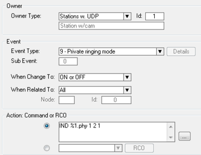
Event 1 - When the IP SubStation makes a normal call, and the other party is set to Private. (DAK 11 is programmed to I133)
| Event Owner: | Stations w. UDP, Id: 2 (Stations w/monitor) |
| Event type: | 9 – Private Ringing Mode |
| Subevent: | n/a |
| When change to: | ON or OFF |
| When related to: | Stations w. UDP, Id: 1 (Stations w/cam) |
| Action: | IND %2.phy 1 2 1 |
Explanation: The event will trigger when a station (the related to) calls a station (the owner) which is in private mode. The owner station will then ring, and the ringing is also heard in the related to station (the initiator).
IND %2.phy 1 2 1 commands station %2.phy (which is equal to the physical number of the related to station) to turn on (or off, depending on the "When Change To" state) the amber LED to the "bell"
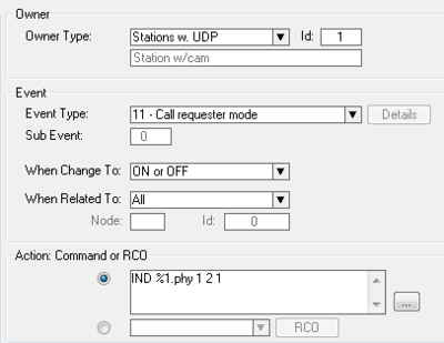
Event 2 - When the IP SubStation makes a call request. (DAK 11 is programmed to I623 I133)
| Event Owner: | Stations w. UDP, Id: 1 (Stations w/cam) |
| Event type: | 11 – Call Requester Mode |
| Subevent: | n/a |
| When change to: | ON or OFF |
| When related to: | All |
| Action: | IND %1.phy 1 2 1 |
Explanation: The event will trigger when a station (the owner) makes a call request to another station (the related to). The owner station will then be put into Call Requester Mode and ring.
IND %1.phy 1 2 1 commands station %1.phy (which is equal to the physical number of the owner of the event) to turn on (or off, depending on the "When Change To" state) the amber LED to the "bell"
The "head" LED
The "head" LED is used to indicate that the station is in conversation mode. This mode can be achieved in two ways:
- 1: The IP SubStation has made an ordinary call = Conversation Outgoing
- 2: The IP SubStation has made a Call Request to another station = Conversation Incoming
Depending on the two variants, one of these two following event can be used:
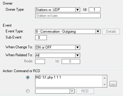
Event 1 - When the IP SubStation makes a normal call, and the other party answer. (DAK 11 is programmed to I133)
| Event Owner: | Stations w. UDP, Id: 1 (Stations w/cam) |
| Event type: | 8 – Conversation Outgoing |
| Subevent: | n/a |
| When change to: | ON or OFF |
| When related to: | All |
| Action: | IND %1.phy 1 1 1 |
Explanation: The event will trigger when a conversation is established between the owner and another station.
IND %1.phy 1 1 1 commands station %1.phy (which is equal to the physical number of the owner station) to turn on (or off, depending on the "When Change To" state) the amber LED to the "head"
Event 2 - When the call request form the IP SubStation is answered. (DAK 11 is programmed to I623 I133)
| Event Owner: | Stations w. UDP, Id: 1 (Stations w/cam) |
| Event type: | 7 – Conversation Incoming |
| Subevent: | n/a |
| When change to: | ON or OFF |
| When related to: | All |
| Action: | IND %1.phy 1 1 1 |
Explanation: The event will trigger when a call request from the station (the owner) is answered by the other party. The conversation is then actually set up by the pther party, thus making it an incoming conversation for the event owner.
IND %1.phy 1 1 1 commands station %1.phy (which is equal to the physical number of the owner of the event) to turn on (or off, depending on the "When Change To" state) the amber LED to the "head"
The "door" LED
The "door" LED is used to indicate that the onboard station relay is activated to operate the door lock. Unlike the previous events, this must be configured for each station individually.
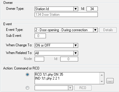
Event 1 - When the related to station (the station with the monitor) dials 6 during conversation to operated the door, the onboard relay is operated, and the "door" LED is lit for 3.5 seconds.
| Event Owner: | Stations Id, Id: 34 (134 Door Station) |
| Event type: | 2 – Door Opening - During Conversation |
| Subevent: | n/a |
| When change to: | ON or OFF |
| When related to: | All |
| Action: | RCO %1.phy ON 35 |
| IND %1.phy 2 2 1 |
Explanation:
The event will trigger when 6 is dialed during conversation by the remote party. The event will turn on the RCO equal to the physical number of the event owner (the IP SubStation) for 3.5 seconds. In addition it will activate the green "door" LED for the duration of the event (default 3.5 seconds).


