RCI - Remote Control Input: Difference between revisions
From Zenitel Wiki
No edit summary |
m (Roarl moved page RCI - Remote Contol Input to RCI - Remote Control Input) |
||
| (25 intermediate revisions by 2 users not shown) | |||
| Line 1: | Line 1: | ||
{{A}} | |||
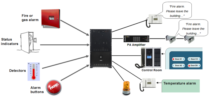
[[File:RCI Usage.PNG|thumb|700px|Examples of RCI usage]] | [[File:RCI Usage.PNG|thumb|700px|Examples of RCI usage]] | ||
A '''Remote Control Input (RCI)''' is triggered by an external potential-free contact. | A '''Remote Control Input (RCI)''' is triggered by an external potential-free contact. | ||
| Line 17: | Line 18: | ||
! style="background:#ffdead;" width="70" |# of RCI's | ! style="background:#ffdead;" width="70" |# of RCI's | ||
|- | |- | ||
| [[AlphaCom_XE1#Remote_Control_Inputs_.28RCI.29|AlphaCom XE1]] || align=center | | | [[AlphaCom_XE1#Remote_Control_Inputs_.28RCI.29|AlphaCom XE1]] || align=center | 0 | ||
|- | |- | ||
| [[AlphaCom_XE7#Remote_Control_Inputs_.28RCI.29|AlphaCom XE7]] || align=center | 2 | | [[AlphaCom_XE7#Remote_Control_Inputs_.28RCI.29|AlphaCom XE7]] || align=center | 2 | ||
| Line 24: | Line 25: | ||
|- | |- | ||
| [[AlphaCom_XE26#Remote_Control_Inputs_.28RCI.29|AlphaCom XE26]] || align=center | 6 | | [[AlphaCom_XE26#Remote_Control_Inputs_.28RCI.29|AlphaCom XE26]] || align=center | 6 | ||
|- | |||
| ENA Amplifier || align=center | 6 | |||
|- | |- | ||
| [[IPARIO|IPARIO unit]] (IP) || align=center | 8 | | [[IPARIO|IPARIO unit]] (IP) || align=center | 8 | ||
| Line 29: | Line 32: | ||
| [[RIO|RIO unit]] (analog) || align=center | 8 | | [[RIO|RIO unit]] (analog) || align=center | 8 | ||
|- | |- | ||
| [[:Category: | | [[:Category:Stations#INCA_stations|INCA Station]] || align=center | 3 | ||
|- | |- | ||
| [[:Category: | | [[:Category:Stations#Turbine_stations|Turbine station]] || align=center | 6 | ||
|- | |- | ||
|} | |} | ||
Select a device from the above table to see details on connections and configuration | Select a device from the above table to see details on connections and configuration | ||
== Actions == | == Actions == | ||
| Line 53: | Line 53: | ||
== Configuration == | == Configuration == | ||
===Inputs from AlphaCom, IPARIO and RIO === | ===Inputs from AlphaCom, ENA Amplifier, IPARIO and RIO === | ||
In [[AlphaPro]] there is an [[Exchange_%26_System_%28AlphaPro%29#RCI|RCI table]], where the physical address of the input is entered, along with the desired actions. The physical address is given as [[device]] + pin-number. | In [[AlphaPro]] there is an [[Exchange_%26_System_%28AlphaPro%29#RCI|RCI table]], where the physical address of the input is entered, along with the desired actions. The physical address is given as [[device]] + pin-number. | ||
The RCI table supports up to 140 inputs. | The RCI table supports up to 140 inputs. | ||
* For internal RCIs in the AlphaCom, the device address is 65-68, and the pin number is 1-6. | * For internal RCIs in the AlphaCom, the device address is 65 (66-68 for Slave Modules), and the pin number is 1-6. | ||
* Internal pin number 8 is the [[Temperature Alarm|temperature alarm]]. | * Internal pin number 8 is the [[Temperature Alarm|temperature alarm]]. | ||
* Mappings for the internal RCI's are [[Autoload|autoloaded]]. Mappings for external RCI's (Slave modules, RIO's or IPARIO) must be manually programmed. | * Mappings for the internal RCI's are [[Autoload|autoloaded]]. Mappings for external RCI's (ENA amplifiers, Slave modules, RIO's or IPARIO) must be manually programmed. | ||
{| border="1" | {| border="1" | ||
! style="background:#ffdead;" width="200" | | ! style="background:#ffdead;" width="200" | | ||
! style="background:#ffdead;" width="70" |RCI Type | ! style="background:#ffdead;" width="70" |'''RCI Type''' | ||
! style="background:#ffdead;" width=" | ! style="background:#ffdead;" width="120" |'''Device/Station physical Number''' | ||
! style="background:#ffdead;" width="70" |Pin Number | ! style="background:#ffdead;" width="70" |'''Pin Number''' | ||
|- | |- | ||
| AlphaCom XE20/XE26 || align=center | Device || align=center | 65 | | AlphaCom XE20/XE26 || align=center | Device || align=center | 65 || align=center | 1 - 6 | ||
|- | |- | ||
| AlphaCom XE7/XE1 || align=center | Device || align=center | 65 - | | AlphaCom XE7/XE1 || align=center | Device || align=center | 65 || align=center | 1 - 2 | ||
|- | |||
| ENA Amplifier || align=center | Station || align=center | 1 - 552 || align=center | 1 - 6 | |||
|- | |- | ||
| [[IPARIO|IPARIO unit]] (IP) || align=center | Station || align=center | 1 - 552 || align=center | 1 - 8 | | [[IPARIO|IPARIO unit]] (IP) || align=center | Station || align=center | 1 - 552 || align=center | 1 - 8 | ||
| Line 78: | Line 80: | ||
Example configuration: | Example configuration: | ||
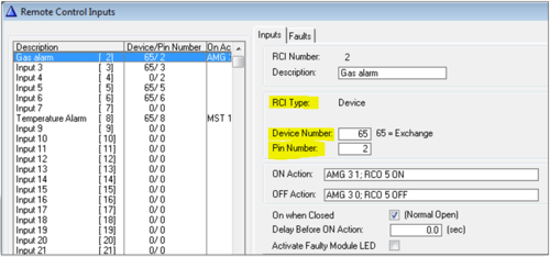
[[File:RCI AlphaPro.png|left|thumb|500px|RCI configuration window. Here input 2 will trigger voice alarm message number | [[File:RCI AlphaPro.png|left|thumb|500px|RCI configuration window. Here input 2 will trigger voice alarm message number 1 to group 3, and turn on the RCO 5]] | ||
<br style="clear:both;" /> | <br style="clear:both;" /> | ||
<br><br> | |||
===Inputs from IP Stations=== | ===Inputs from IP Stations/Devices=== | ||
Inputs from IP Stations must be configured using the Event Handler. | Inputs from IP Stations must be configured using the Event Handler. | ||
{| border="1" | {| border="1" | ||
! style="background:#ffdead;" width="200" |Hardware | ! style="background:#ffdead;" width="200" |'''Hardware''' | ||
! style="background:#ffdead;" width=" | ! style="background:#ffdead;" width="160" | '''Event Owner = Station Physical Number''' | ||
! style="background:#ffdead;" width=" | ! style="background:#ffdead;" width="150" |'''Physical Input number''' | ||
! style="background:#ffdead;" width=" | ! style="background:#ffdead;" width="120" | '''Sub-Event''' | ||
|- | |- | ||
| [[INCA Substation Board Connectors|IP Substation]] || align=center | 1 - 552 || align=center | 1 - 3 || align=center | 1 - 3 | | [[INCA Substation Board Connectors|IP Substation]] || align=center | 1 - 552 || align=center | 1 - 3 || align=center | 1 - 3 | ||
| Line 95: | Line 98: | ||
|- | |- | ||
| [[:Category:Turbine Connections|IP Turbine station]] || align=center | 1 - 552 || align=center | 1 - 6 || align=center | 11 - 16 (**) | | [[:Category:Turbine Connections|IP Turbine station]] || align=center | 1 - 552 || align=center | 1 - 6 || align=center | 11 - 16 (**) | ||
|- | |||
| [[IP-LCM]] || align=center | 1 - 552 || align=center | TKIS I/O input 1-6 <br> Additional input 1 - 8 || align=center | 11-16 <br> 18 - 25 | |||
|- | |- | ||
|} | |} | ||
| Line 107: | Line 112: | ||
In the Event Handler, use the following parameters: | In the Event Handler, use the following parameters: | ||
* '''Owner''': The station where the input is used | * '''Owner''': The station/device where the input is used | ||
*'''Event type''': 30 - Station DAK as RCI | *'''Event type''': 30 - Station DAK as RCI | ||
*'''Sub-Event''': The input number according to the table above | *'''Sub-Event''': The input number according to the table above | ||
| Line 114: | Line 119: | ||
Example configuration: | Example configuration: | ||
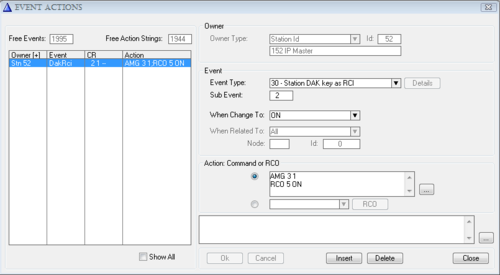
[[File:DakAsRCI.PNG|left|thumb|500px|Event Handler configuration window. Here Input 2 (DAK 2) will trigger alarm message | [[File:DakAsRCI.PNG|left|thumb|500px|Event Handler configuration window. Here Input 2 (DAK 2) will trigger alarm message 1 to group 3, and turn on RCO 5]] | ||
<br style="clear:both;" /> | <br style="clear:both;" /> | ||
Latest revision as of 12:15, 9 February 2023
A Remote Control Input (RCI) is triggered by an external potential-free contact.
Inputs
Typical external triggers can be:
- Fire and gas alarm systems
- Temperature detectors
- Doors sensors
- Lift status
- Alarm buttons
An RCI signal can be received by a number of devices:
| Device | # of RCI's |
|---|---|
| AlphaCom XE1 | 0 |
| AlphaCom XE7 | 2 |
| AlphaCom XE20 | 6 |
| AlphaCom XE26 | 6 |
| ENA Amplifier | 6 |
| IPARIO unit (IP) | 8 |
| RIO unit (analog) | 8 |
| INCA Station | 3 |
| Turbine station | 6 |
Select a device from the above table to see details on connections and configuration
Actions
The set-up for the RCI input and the actions you want it to activate is very flexible. An RCI can activate almost any function in the exchange by using action commands, either Built-In Action Commands or Data Protocol Commands. The configuration of the RCI's is done with the AlphaPro programming tool.
Some examples of features that can be activated:
- Dispatch prerecorded voice messages to stations and PA system (fire alarm etc.)
- Show status information on a DAK48 panel, e.g. door open/closed
- Send text message to a station or a group of stations, e.g. temperature warning
- Set up group calls, audio program or conferences
- Activate Call Forwarding
- Control Remote Control Output
etc.
Configuration
Inputs from AlphaCom, ENA Amplifier, IPARIO and RIO
In AlphaPro there is an RCI table, where the physical address of the input is entered, along with the desired actions. The physical address is given as device + pin-number.
The RCI table supports up to 140 inputs.
- For internal RCIs in the AlphaCom, the device address is 65 (66-68 for Slave Modules), and the pin number is 1-6.
- Internal pin number 8 is the temperature alarm.
- Mappings for the internal RCI's are autoloaded. Mappings for external RCI's (ENA amplifiers, Slave modules, RIO's or IPARIO) must be manually programmed.
| RCI Type | Device/Station physical Number | Pin Number | |
|---|---|---|---|
| AlphaCom XE20/XE26 | Device | 65 | 1 - 6 |
| AlphaCom XE7/XE1 | Device | 65 | 1 - 2 |
| ENA Amplifier | Station | 1 - 552 | 1 - 6 |
| IPARIO unit (IP) | Station | 1 - 552 | 1 - 8 |
| RIO unit (analog) | Device | 1 - 64 | 1 - 8 |
Example configuration:
Inputs from IP Stations/Devices
Inputs from IP Stations must be configured using the Event Handler.
| Hardware | Event Owner = Station Physical Number | Physical Input number | Sub-Event |
|---|---|---|---|
| IP Substation | 1 - 552 | 1 - 3 | 1 - 3 |
| IP Flush Master and IP OR | 1 - 552 | 1 - 3 | 11 - 13 (*) |
| IP Turbine station | 1 - 552 | 1 - 6 | 11 - 16 (**) |
| IP-LCM | 1 - 552 | TKIS I/O input 1-6 Additional input 1 - 8 |
11-16 18 - 25 |
Important notes:
(*): When set as station type "Master station" in AlphaPro, the inputs are mapped as Sub-Event 11, 12 and 13. When set as "CRM" the inputs are mapped as Sub-Event 251, 252 and 253.
(**): On Turbine stations, the Sub-Event number depends on the AMC software version:
- AMC 11.2.3.9 and lower: Sub-Event number is 1 - 6
- AMC 11.2.3.10: Sub-Event number is 101 - 106
- AMC 11.2.3.11 and higher: Sub-Event number is 11 - 16
In the Event Handler, use the following parameters:
- Owner: The station/device where the input is used
- Event type: 30 - Station DAK as RCI
- Sub-Event: The input number according to the table above
- When Change to: ON = Input goes on. OFF = input goes off.
Example configuration:
See also:
Software
- AMC 10.50 or later supports RCI's in slave module (devices 66-68). (The software in the slave modules must also be upgraded)


