RCO - Remote Control Output: Difference between revisions
From Zenitel Wiki
No edit summary |
|||
| Line 12: | Line 12: | ||
==Devices supporting RCOs== | ==Devices supporting RCOs== | ||
RCO outputs are available on a number of devices: | |||
{| border="1" | {| border="1" | ||
| Line 40: | Line 40: | ||
|} | |} | ||
( | ''(x): When the [[ATLB-12]] board is used in [[ATLB in AlphaCom E7 - RCO's|AlphaCom XE7 only four RCOs]] are available'' | ||
<br><br> | <br><br> | ||
Revision as of 11:32, 28 May 2014
The Remote Control Output RCO’s are used to operate relays for control of external equipment.
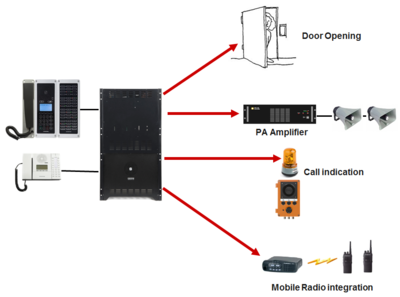
Relay outputs are typically used for:
- Door opening
- PA control
- Call indication
- Queue indication
- Keying of mobile radio transmitter
- CCTV interface
Devices supporting RCOs
RCO outputs are available on a number of devices:
| Device | # of RCO's | Comment | Hardware required |
|---|---|---|---|
| AlphaCom XE26 | 138 | 6 RCOs per ASLT card or ATLB-12 card | MRBD relay board + PDB Power Distribution Board |
| AlphaCom XE20 | 102 | 6 RCOs per ASLT card or ATLB-12 card | MRBD relay board |
| AlphaCom XE7 | 12 | Need ASLT or ATLB-12 in position 1 and 2 (x) | MRBD relay board |
| AlphaCom XE1 | 0 | RCOs not available. Use IPARIO unit | IPARIO unit |
| IPARIO unit (IP) | 8 | Remote outputs over IP network | IPARIO unit |
| RIO unit (analog) | 18 | Remote outputs over RS232/485 | MRBD relay board |
| IP Substation board (PCB 8022) | 2 | One relay on connector P3, pin 3/4 | The second output is a logical signal. Transistor + relay required |
| IP Flush Master/IP OR station (PCB 8024) | 2 | One relay on connector P3, pin 3/4 | The second output is a logical signal. Transistor + relay required |
| Turbine Compact/TKIS-2 kit | 7 | One relay included | Use MRBD relay board if more than 1 relay is needed |
(x): When the ATLB-12 board is used in AlphaCom XE7 only four RCOs are available
Logical RCOs
There are several ways to control RCOs, the most commonly used one is to use Logical RCOs controlled by the RCO command.
- The RCO command operates a Logical RCO
- Each logical RCO must be mapped to a Device or Station, and to a Pin Number
- The AlphaCom XE software supports up to 500 logical RCOs.
- The operation of the logical RCOs is configured from AlphaPro, in the Event Handler window.
Mapping of RCOs
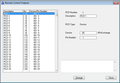
The mapping of RCOs are done from AlphaPro, Exchange & System -> RCO window where the logical RCO is assigned to a physical address. The physical address is given as Device + Pin Number or by Station + Pin Number.
| RCO number: | The "logical" number of the RCO. Use this number in the RCO command. |
| Description: | Any text. This information is stored in the AlphaPro database only, and is not sent to the exchange. |
| RCO Type: | Device: The AlphaCom (i.e. ASLT or ATLB-12 board) or RIO unit Station: IP Station, Turbine or IPARIO |
| Device: |
|
| Pin number: |
|
- RCO 1-138 is by default mapped to the internal RCOs in the AlphaCom, i.e. device 65 - pin 1 to device 65 - pin 138
- Mappings for all other RCOs must be configured manually
- The RCOs can be used freely within the system, e.g. an event on one station can operate an RCO located on a different station.
- The exchange always keeps track of the state of an output in case the device becomes faulty. When a faulty device becomes OK again, the exchange will restore the current RCO state.
Configuration examples
The Event Handler is used to configure the behavior of the RCOs. Here are some examples:
- Door opening and Code lock
- Call indication
- CCTV integration using relays
- CCTV control by relays (RCO) when using Call Request
- PA Interface
Software
- AMC 10.50 or later to control RCOs in slave modules. Earlier AMC versions support RCOs in master module only (pin 1 - 138).
- AMC 10.04: Additional parameter to pulse the RCO ('RCO 12 ON 20' to generate a 2.0 sec pulse on RCO 12)
- AMC 07.40 or later to control RCOs in an AlphaNet installation.


