ATLB in AlphaCom E7 - RCO's
From Zenitel Wiki

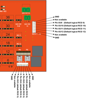
The RCO pinout towards the backplane is different on the ASLT and the ATLB.
In the AlphaCom XE20/XE26 the ATLB connection board and the RJ45 filter board is adjusted accordingly, so the RCO's comes out correctly.
But in the AlphaCom XE7 there is a direct connection from board pos. 1 and 2 to the RCO 1-6 and 7-12, designed for the ASLT card pinout.
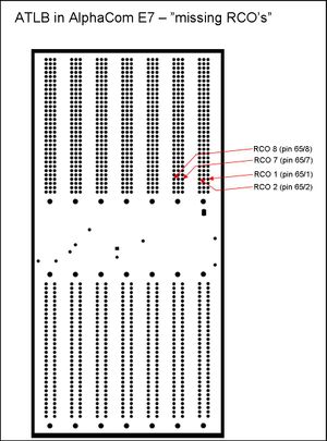
When using ATLB in AlphaCom XE7 only four RCO's are available on the RCO pinheader, and they come out on different pins than what you expect:

ATLB in board position 1:
- Logical RCO 1 (65/1) is not available
- Logical RCO 2 (65/2) is not available
- Logical RCO 3 (65/3) triggers physical RCO 2
- Logical RCO 4 (65/4) triggers physical RCO 3
- Logical RCO 5 (65/5) triggers physical RCO 4
- Logical RCO 6 (65/6) triggers physical RCO 5
ATLB in board position 2:
- Logical RCO 7 (65/7) is not available
- Logical RCO 8 (65/8) is not available
- Logical RCO 9 (65/9) triggers physical RCO 8
- Logical RCO 10 (65/10) triggers physical RCO 9
- Logical RCO 11 (65/11) triggers physical RCO 10
- Logical RCO 12 (65/12) triggers physical RCO 11

The two RCO's which are not available on the RCO pinheader are located on the backplane of the AlphaCom XE7. If these RCO's are neeeded, it is possible to solder wires to these pins, and connect the wire to the input of the MRBD board directly. Switch the power off, and remove the cover plate to reveal the backplane connectors. Replace the cover plate when the soldering is finnished.
