ENA Amplifier Configuration (SIP): Difference between revisions
From Zenitel Wiki
(→RCOs) |
|||
| (51 intermediate revisions by the same user not shown) | |||
| Line 109: | Line 109: | ||
=== DAVC === | === DAVC === | ||
The Distributed Automatic Volume Control (DAVC) is an algorithm which is using one or more microphones ("AVC Source") to measure the ambient audio/noise level, and | The Distributed Automatic Volume Control (DAVC) is an algorithm which is using one or more microphones ("AVC Source") to measure the ambient audio/noise level, and data from the microphones are used to adjust the loudspeaker output level of the ENA amplifier ("AVC Receiver") according to the ambient audio level. For details, see [[Distributed Automatic Volume Control (DAVC) (SIP)]]. | ||
{{note|This menu option is available when the [[Advanced Configuration Mode (SIP)|Advanced Configuration mode]] is enabled.}} | {{note|This menu option is available when the [[Advanced Configuration Mode (SIP)|Advanced Configuration mode]] is enabled.}} | ||
| Line 115: | Line 115: | ||
=== GPI Settings === | === GPI Settings === | ||
[[File:ENA | An input can be used to initiate and tear down a call between a user and an amplifier channel. | ||
[[File:ENA GPI.PNG|thumb|left|700px|The '''GPI Settings''' page]] | |||
<br style="clear:both;" /> | <br style="clear:both;" /> | ||
| Line 126: | Line 128: | ||
*'''Idle:''' Call Destination | *'''Idle:''' Call Destination | ||
*'''Call:''' Hangup Call | *'''Call:''' Hangup Call | ||
Inputs can also be used to report faults from external system/devices via SNMP Trap. See [[#External_Custom_Faults|External_Custom_Faults]] | |||
<br> | <br> | ||
| Line 134: | Line 138: | ||
=== Multicast Paging === | === Multicast Paging === | ||
Multicast Paging enables | Multicast Paging enables the ENA amplifier to receive RTP multicast streaming from e.g. 3rd party iPBX (e.g. Asterisk). Up to 10 different Multicast paging groups can be defined. | ||
For | For details, see [[Multicast Paging (Edge/SIP)]] | ||
{{note|This menu option is available when the [[Advanced Configuration Mode (SIP)|Advanced Configuration mode]] is enabled.}} | {{note|This menu option is available when the [[Advanced Configuration Mode (SIP)|Advanced Configuration mode]] is enabled.}} | ||
| Line 280: | Line 284: | ||
===Specific Settings === | ===Specific Settings === | ||
These settings are made for specific projects, and should be left disabled. | These settings are made for specific projects, and should be left disabled. | ||
[[File:ENA SpecificSetttings.PNG|thumb|left| | [[File:ENA SpecificSetttings.PNG|thumb|left|701px|The '''Specific Settings''' page in an ENA2060 amplifier]] | ||
<br style="clear:both;" /> | <br style="clear:both;" /> | ||
| Line 310: | Line 314: | ||
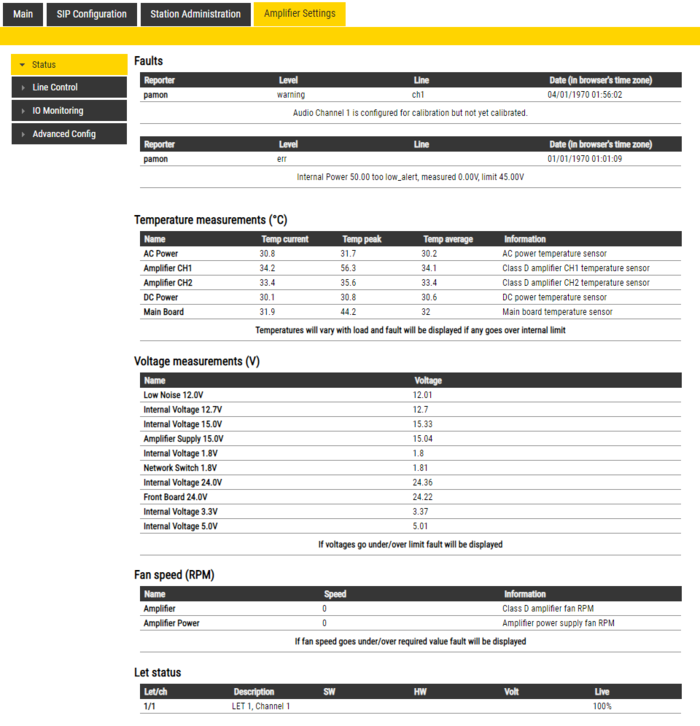
** Only faults that are active for enabled monitoring options are visible | ** Only faults that are active for enabled monitoring options are visible | ||
** If the page is empty there are no reported faults | ** If the page is empty there are no reported faults | ||
*'''Temperature measurements''' | *'''Temperature measurements''': Display different temperature levels | ||
* '''Voltage measurements''': Display measured voltage levels for diagnostics | |||
* '''Voltage measurements''' | * '''Fan speed (RPM)''': Display the fan speed for the two fans inside the amplifier (Not applicable to the ENA2060 amplifier) | ||
* '''Let status''': If there are Let configured for the amplifier the status will be displayed here | |||
* '''Fan speed (RPM)''' | |||
* '''Let status''' | |||
=== Line Control === | === Line Control === | ||
==== Line Control - ENA2x00-AC2==== | |||
==== ENA2x00-AC2==== | |||
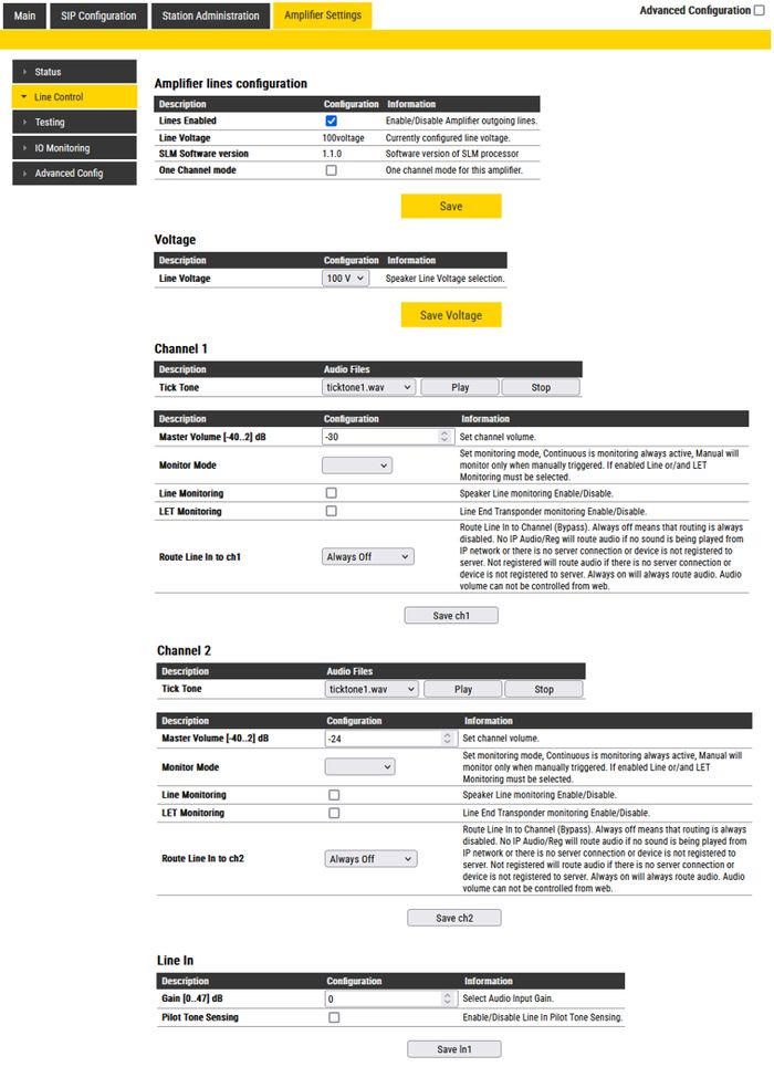
[[File:ENA2x00-AC2 LineControl.jpg|thumb|left|700px|The '''Line Control''' page in ENA2x00-AC2]] | [[File:ENA2x00-AC2 LineControl.jpg|thumb|left|700px|The '''Line Control''' page in ENA2x00-AC2]] | ||
<br style="clear:both;" /> | <br style="clear:both;" /> | ||
<br> | <br> | ||
'''Amplifier Lines configuration''': | |||
* '''Lines Enabled''': Enable/Disable Amplifier outgoing lines. | |||
* '''Line Voltage''': Shows urrently configured line voltage. | |||
* '''SLM Software version''': Shows the software version of SLM processor | |||
* '''One Channel mode''': [[ENA2x00-AC2 - One Channel Mode|One channel mode]] for this amplifier. | |||
'''Voltage''' options: | '''Voltage''' options: | ||
| Line 349: | Line 336: | ||
'''Channel 1'''/'''Channel 2''' options: | '''Channel 1'''/'''Channel 2''' options: | ||
* ''' | * '''Tick Tone''': A tick tone can be sent to the channel. This function can be used to audibly verify that the system works properly. The tick tone is a “clicking sound”. | ||
* '''Master Volume''' in dB | * '''Master Volume''' in dB. Sets the channel volume. | ||
* '''Monitor Mode''' can be '''Off''', '''Manual''' for manual monitor triggering and '''Continuous''' for continuous monitoring | * '''Monitor Mode''' can be '''Off''', '''Manual''' for manual monitor triggering and '''Continuous''' for continuous monitoring | ||
** To get access to monitoring configuration options, either type of monitoring has to be enabled | ** To get access to monitoring configuration options, either type of monitoring has to be enabled | ||
* ''' | * '''Line Monitoring''' enables Speaker Line Monitoring (SLM) | ||
* '''LET Monitoring''' enables [[ELTSI-1|Line End Transponder]] monitoring | |||
* '''Route Line In to ch''' Route Line In to Channel (Bypass). '''Always off''' means that routing is always disabled. '''No IP Audio/Reg''' will route audio if no sound is being played from IP network or there is no server connection or device is not registered to server. '''Not registered''' will route audio if there is no server connection or device is not registered to server. '''Always on''' will always route audio. Volume can be adjusted by a pot-meter at the rear side of the amplifier. Volume can not be controlled from web. | |||
** ** See more details at [[ENA amplifier in Bypass Mode]] | |||
'''Line In''' options: | '''Line In''' options: | ||
* ''' | * '''Gain''': Select Audio Input Gain. | ||
* '''Pilot Tone Sensing''' Enable/Disable Line In Pilot Tone Sensing | * '''Pilot Tone Sensing''' Enable/Disable Line In Pilot Tone Sensing | ||
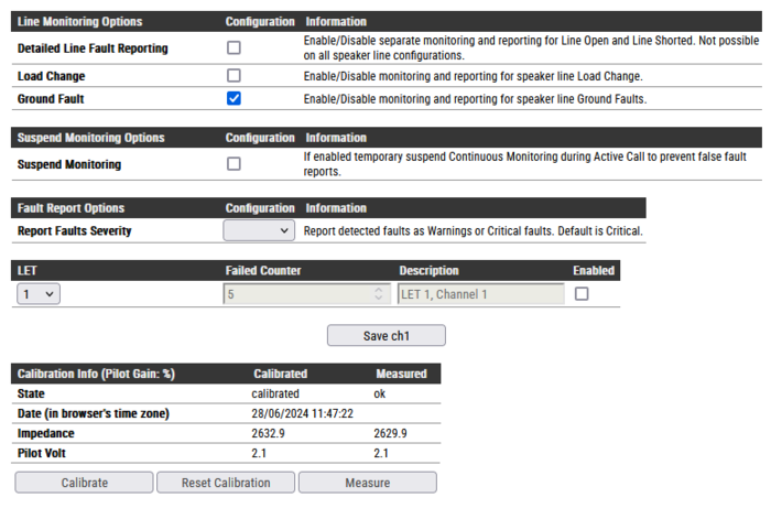
==== Monitoring options ==== | ===== Line Monitoring options ===== | ||
Line monitoring options become available when '''Monitoring Mode''' is set to '''Continuous''' or '''Manual''', and '''Line Monitoring''' is enabled | |||
[[File:ENA LinMonOpt.PNG|thumb|left|700px|Line Monitoring options]] | |||
<br style="clear:both;" /> | |||
** '''Detailed Line Fault Reporting''' will enable separate reporting of open and shorted, not available on all speaker line configurations | ** '''Detailed Line Fault Reporting''' will enable separate reporting of open and shorted, not available on all speaker line configurations | ||
** '''Load Change''' monitor line load change | ** '''Load Change''' monitor line load change | ||
| Line 389: | Line 371: | ||
** '''Reset Calibration''' ('''3 seconds''' timeout) will reset channel calibration | ** '''Reset Calibration''' ('''3 seconds''' timeout) will reset channel calibration | ||
** '''Measure''' ('''60 second''' timeout, only available if '''Monitor Mode''' is '''Manual''' and channel is successfully calibrated) will manual monitor channel for 60 seconds and report any faults detected | ** '''Measure''' ('''60 second''' timeout, only available if '''Monitor Mode''' is '''Manual''' and channel is successfully calibrated) will manual monitor channel for 60 seconds and report any faults detected | ||
<br> | |||
==== Line Control - ENA2060==== | |||
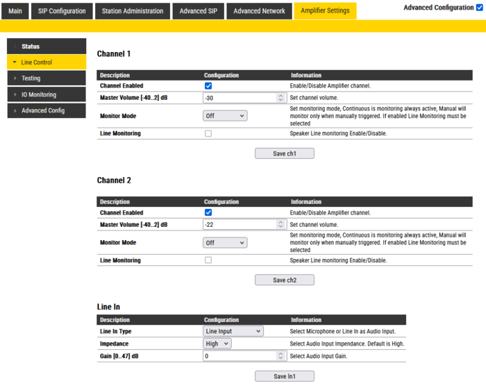
[[File:ENA2060 LineCtrl.PNG|thumb|left|700px|The '''Line Control''' page in ENA2060]] | |||
<br style="clear:both;" /> | |||
<br> | |||
'''Channel 1'''/'''Channel 2''' options: | |||
* '''Channel Enabled''': Enable/Disable Amplifier channel. | |||
* '''Master Volume''' in dB. Sets the channel volume. | |||
* '''Monitor Mode''': Set monitoring mode, '''Continuous''' is monitoring always active, '''Manual''' will monitor only when manually triggered. '''Line Monitoring''' must be enabled as well. | |||
* '''Line Monitoring''' enables Speaker Line Monitoring (SLM). See [[ENA2060 Amplifier - Speaker Line Monitoring]] | |||
'''Line In''' options: | |||
* '''Line In Type''': Select "Microphone" (pin 21/22 on the [[ENA2060_Amplifier_-_Mounting_and_Installation#Multi-Connector|multi-connector]]) or "Line In" (pin 16/17 on the [[ENA2060_Amplifier_-_Mounting_and_Installation#Multi-Connector|multi-connector]]) as Audio Input. | |||
* '''Impedance''': Select Audio Input Impedance. Default is High. | |||
* '''Gain''': Select Audio Input Gain. | |||
<br> | |||
=== Testing === | === Testing === | ||
| Line 402: | Line 405: | ||
=== IO Monitoring === | === IO Monitoring === | ||
The ENA amplifier offers monitoring of the outputs and the inputs | The ENA amplifier offers monitoring of the outputs and the inputs. | ||
==== RCOs ==== | ==== RCOs ==== | ||
The '''RCOs''' monitoring alerts when the voltage on the contacts of an output is outside the configured legal value. | |||
*'''Limit Low OK''' - If the RCO triggers and the voltage is below this value, it is reported as "Shorted". | |||
*'''Limit High Not OK''' - If the RCO is not above this voltage when output is high, it is reported as an "Overload". | |||
The RCOs can be tested from this page. They can be set and cleared. Remember to set them back to '''System''' before ending the test. | |||
[[File:ENA IOs RCOs.PNG|thumb|left|700px|IO Monitoring > RCOs]] | [[File:ENA IOs RCOs.PNG|thumb|left|700px|IO Monitoring > RCOs]] | ||
<br style="clear:both;" /> | <br style="clear:both;" /> | ||
Latest revision as of 13:45, 28 June 2024
This article describes the configuration settings available via the web interface of the ENA IP Network Amplifier in SIP mode.
Notes

|
|
Main
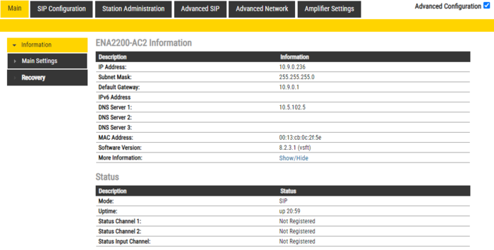
Information
- Log In to the amplifier
- The Information page will now be displayed, showing the amplifier configuration and status.

|
|
Main Settings
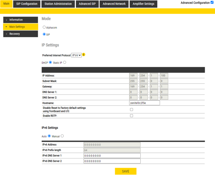
- Click Station Main > Main Settings to access the page for configuring Station Mode and IP parameters.
Mode: Select the SIP radio-button.
Preferred Internet Protocol: Select either IPV4 or IPV6. (Not available in the ENA2060 amplifier).
IP Settings:
- DHCP – Select this option if the IP station shall receive IP Settings from a DHCP server.
- Static IP – Select this option if the IP station shall use a static IP address. Enter values for:
- - IP-address
- - Subnet-mask
- - Gateway
- - DNS Server 1 (option for network administration)
- - DNS Server 2 (option for network administration)
- - Hostname (option for network administration)
- Disable Reset to Factory default settings using frontboard and I/O: If enabled, factory reset will only be possible from the web interface. This is disabled by default.
- Enable RSTP: RSTP is only required when using redundant networking (Not available in the ENA2060 amplifier).
Click Save followed by Apply to apply the new configuration settings.
Time Settings (Available in the ENA2060 amplifier only).
- Enable Network Time Protocol, set the IP address of the NTP Server, Select Region and Zone
Recovery
- Full reboot: Perform a full Linux reboot. No configuration is lost
- Partial reboot: Perform a restart of the intercom application. No configuration is lost
- Factory reset: Set all parameters to Factory Default values. The amplifier will get static IP Address 169.254.1.100.
- Factory reset with DHCP: Set all parameters to Factory Default values. The amplifier will get IP Address from DHCP server. If no DHCP server in the network, it will get a random 169.254.x.x IP address.
SIP Configuration
Account/Call
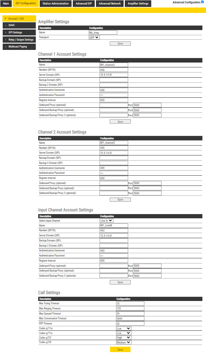
Select SIP Configuration -> Account/Call to access the page for configuring the SIP Account Settings.
Amplifier Settings
- Name: Enter a name for the amplifier.
- Transport: Transport protocol to use for SIP. Choose between UDP (default), TCP or TLS.
Channel 1/2 Account Settings
- Name: Enter a name that will be shown on the display at the remote party.
- Number (SIP ID): This is the identification of the station in the SIP domain, i.e. the phone number for the station. This parameter is mandatory. Enter the SIP ID in integers according to the SIP account on the SIP domain server.
- Server Domain (SIP): The IP address of the SIP Server. This can be either an IP address in regular dot notation or a hostname.
- Backup Domain (SIP): This is the secondary (or fallback) domain. If the station loses connection to the primary SIP domain, it will switch over to the secondary one. This can be either an IP address in regular dot notation or hostname.
- Backup Domain 2 (SIP): This is the tertiary SIP domain used as backup in case the primary and secondary domains fail. This can be either an IP address in regular dot notation or hostname.
- Authentication User Name: This is the authentication user name used to register the station to the SIP server. This is required only if the SIP server requires authentication and is normally the same as the SIP ID.
- Authentication Password: The authentication user password used to register the station to the SIP server. This is required only if the SIP server requires authentication
- Register Interval: This parameter specifies how often the station will register, and reregister in the SIP domain. This parameter will affect the time it takes to detect that a connection to a SIP domain is lost. Enter the values in number of seconds from 60 to 999999. The default interval is 600 seconds.
- Outbound Proxy [optional]: Enter the IP address of the outbound proxy server in regular dot notation, e.g. 10.5.2.100, or as a hostname.
- Outbound Backup Proxy [optional]: Enter the IP address of the outbound proxy server in regular dot notation, e.g. 10.5.2.100, or as a hostname.
- Outbound Proxy 2 [optional]: Enter the IP address of the outbound proxy server in regular dot notation, e.g. 10.5.2.100, or as a hostname.
Input Channel Account Settings
- Select Input Channel: Select between Line Input or Microphone Input.
- Name: Enter a name that will be shown on the display at the remote party.
- Number (SIP ID): This is the identification of the station in the SIP domain, i.e. the phone number for the station. This parameter is mandatory. Enter the SIP ID in integers according to the SIP account on the SIP domain server.
- Server Domain (SIP): The IP address of the SIP Server. This can be either an IP address in regular dot notation or a hostname.
- Backup Domain (SIP): This is the secondary (or fallback) domain. If the station loses connection to the primary SIP domain, it will switch over to the secondary one. This can be either an IP address in regular dot notation or hostname.
- Backup Domain 2 (SIP): This is the tertiary SIP domain used as backup in case the primary and secondary domains fail. This can be either an IP address in regular dot notation or hostname.
- Authentication User Name: This is the authentication user name used to register the station to the SIP server. This is required only if the SIP server requires authentication and is normally the same as the SIP ID.
- Authentication Password: The authentication user password used to register the station to the SIP server. This is required only if the SIP server requires authentication
- Register Interval: This parameter specifies how often the station will register, and reregister in the SIP domain. This parameter will affect the time it takes to detect that a connection to a SIP domain is lost. Enter the values in number of seconds from 60 to 999999. The default interval is 600 seconds.
- Outbound Proxy [optional]: Enter the IP address of the outbound proxy server in regular dot notation, e.g. 10.5.2.100, or as a hostname.
- Outbound Backup Proxy [optional]: Enter the IP address of the outbound proxy server in regular dot notation, e.g. 10.5.2.100, or as a hostname.
- Outbound Proxy 2 [optional]: Enter the IP address of the outbound proxy server in regular dot notation, e.g. 10.5.2.100, or as a hostname.
Call Settings
- Max Trying Timeout: Default setting 15.
- Max Ringing Timeout: Default setting 120.
- Max Queued Timeout: Default setting 30.
- Max Conversation Timeout: Default setting 3600.
- RTP Timeout: Default setting 3600.
- Codec g711a: Default setting Low.
- Codec g711u: Default setting Low.
- Codec g722: Default setting High.
- Codec g729: Default setting Medium.
DAVC
The Distributed Automatic Volume Control (DAVC) is an algorithm which is using one or more microphones ("AVC Source") to measure the ambient audio/noise level, and data from the microphones are used to adjust the loudspeaker output level of the ENA amplifier ("AVC Receiver") according to the ambient audio level. For details, see Distributed Automatic Volume Control (DAVC) (SIP).

|
This menu option is available when the Advanced Configuration mode is enabled. |
GPI Settings
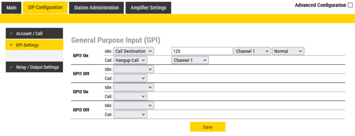
An input can be used to initiate and tear down a call between a user and an amplifier channel.
GPIx On:
- Idle: Call Destination
- Call: Hangup Call
GPIx Off:
- Idle: Call Destination
- Call: Hangup Call
Inputs can also be used to report faults from external system/devices via SNMP Trap. See External_Custom_Faults
Relay/Output Settings
Details are described in this article: GPO Output configuration (ENA amplifier in SIP mode)
Multicast Paging
Multicast Paging enables the ENA amplifier to receive RTP multicast streaming from e.g. 3rd party iPBX (e.g. Asterisk). Up to 10 different Multicast paging groups can be defined.
For details, see Multicast Paging (Edge/SIP)

|
This menu option is available when the Advanced Configuration mode is enabled. |
Station Administration
Change Password
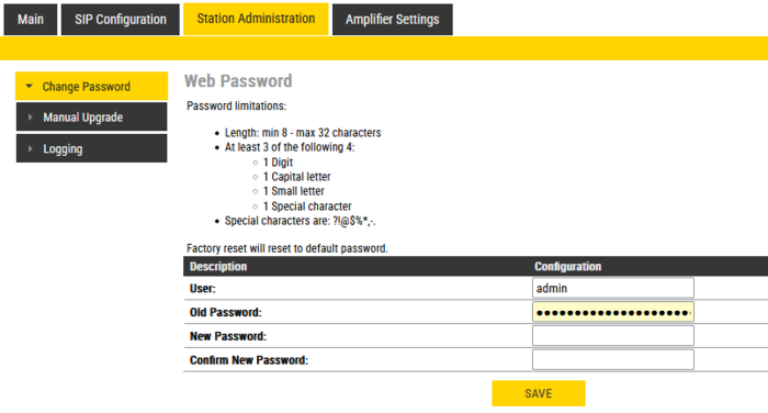
Go to Station Administration -> Change Password
Type in the old password and the new password, then click save.
Device GUI PIN
There is also an option to set a pin code for the Device GUI. A Read only-user and a Full Access-user can be enabled, or changing settings from the GUI can be disabled entirely.
The amplifier arrives with no pin code active by default.
Manual Upgrade
The software of the amplifier can be upgraded via the web interface. see Turbine_Software_Upgrade for details.
Backup and Restore
From the web interface of the amplifier it is possible to backup and restore the configuration data. See Backup and Restore for more information.

|
This menu option is available when the Advanced Configuration mode is enabled. |
Logging
Logs can be useful for debugging and troubleshooting purposes. See Logging - IP Stations on how to enable and collect logs.
Advanced App. Config
This page is used for advanced troubleshooting mainly by developers.

|
This menu option is available when the Advanced Configuration mode is enabled. |
Advanced SIP

|
This menu option is available when the Advanced Configuration mode is enabled. |
Updates
The ENA Amplifier can be configured to automatically poll configuration from a TFTP server. The IP address of this TFTP server can be obtained using DHCP procedures or be manually configured. See TFTP Provisioning for more information.
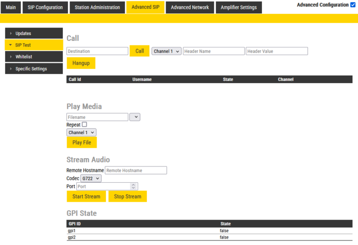
SIP Test
- Call: Insert a directory number to establish a call to. Call is initiated from the Channel 1, Channel 2 or Input Line SIP account when pressing the "Call" button.
- Play Media: Enter a filename, press Play File to play the file. For valid filenames, see below.
- Stream Audio: Select a Remote Hostname, Codec and port, press Start Stream to start streaming audio.
- GPI State: Shows the current state of the GPI.
Play Media
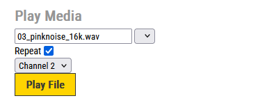
Use this feature to play audio files directly from the amplifier to Channel 1 or 2, or to the Input Line. This can be useful when commissioning the PA system. One can play e.g. the ITU speech simulation file or Pink Noise, and adjust the master volume to appropriate level without the need of setting up calls.
You need to type in the filename as per tables below (the audio files come with the amplifier, no need to upload).
- Check Repeat to play the file in loop
- To stop playing, delete the file name and press "Play File".
Test signals:
| Filename | Description |
|---|---|
| 01_ITUVoice10Sec.wav | Speech simulation file defined by ITU. Useful as test signal when adjusting Master volume of the amplifier |
| 02_whitenoise_16k.wav | White noise |
| 03_pinknoise_16k.wav | Pink noise. Useful as test signal when adjusting Master volume of the amplifier |
| 04_IMD_Test_16k.wav | Description missing |
| 05_adeleshort200Hz.wav | A short clip with Adele |
| 06_sinus0dB.wav | A 1kHz sinus signal |
| 07_sweep_16k.wav | A frequency sweep signal |
Tick Tones: A tick tone can be sent to selected channel/zone. This function can be used to audibly verify that the system works properly. The tick tone is a “clicking sound”.
| Filename | Description |
|---|---|
| ticktone1.wav | Tick tone for testing speaker line |
| ticktone1A.wav | Tick tone for testing speaker line |
| ticktone1B.wav | Tick tone for testing speaker line |
Audio clips:
| Filename | Description |
|---|---|
| twostage_dialing_prompt_code.wav | "Please enter the pin code" |
| twostage_dialing_prompt_directoryid.wav | "Please enter the phone number" |
| twostage_ringing.wav | "Your call has been forwarded, please hold the line" |
Others:
| Filename | Description |
|---|---|
| dingdong.wav | A chime signal |
| readipaddress.wav | The amplifier will play its IP address |
Whitelist
Currently (ver. 8.1.3.1) not in use by ENA amplifiers.
Specific Settings
These settings are made for specific projects, and should be left disabled.
Advanced Network

|
This menu option is available when the Advanced Configuration mode is enabled. |
SNMP
See SNMP in IP Stations for more information.
Firewall
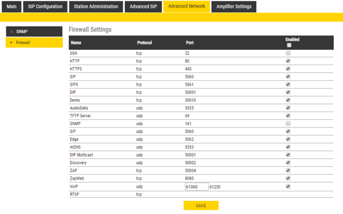
All ENA amplifiers have an embedded firewall. See Firewall for details.
Amplifier Settings
Status
- Faults
- Display currently active faults on amplifier
- The page is automatically refreshed each 10 seconds (can be manually refreshed)
- Only faults that are active for enabled monitoring options are visible
- If the page is empty there are no reported faults
- Temperature measurements: Display different temperature levels
- Voltage measurements: Display measured voltage levels for diagnostics
- Fan speed (RPM): Display the fan speed for the two fans inside the amplifier (Not applicable to the ENA2060 amplifier)
- Let status: If there are Let configured for the amplifier the status will be displayed here
Line Control
Line Control - ENA2x00-AC2
Amplifier Lines configuration:
- Lines Enabled: Enable/Disable Amplifier outgoing lines.
- Line Voltage: Shows urrently configured line voltage.
- SLM Software version: Shows the software version of SLM processor
- One Channel mode: One channel mode for this amplifier.
Voltage options:
- Line Voltage choose speaker line voltage - 70V or 100V options
Channel 1/Channel 2 options:
- Tick Tone: A tick tone can be sent to the channel. This function can be used to audibly verify that the system works properly. The tick tone is a “clicking sound”.
- Master Volume in dB. Sets the channel volume.
- Monitor Mode can be Off, Manual for manual monitor triggering and Continuous for continuous monitoring
- To get access to monitoring configuration options, either type of monitoring has to be enabled
- Line Monitoring enables Speaker Line Monitoring (SLM)
- LET Monitoring enables Line End Transponder monitoring
- Route Line In to ch Route Line In to Channel (Bypass). Always off means that routing is always disabled. No IP Audio/Reg will route audio if no sound is being played from IP network or there is no server connection or device is not registered to server. Not registered will route audio if there is no server connection or device is not registered to server. Always on will always route audio. Volume can be adjusted by a pot-meter at the rear side of the amplifier. Volume can not be controlled from web.
- ** See more details at ENA amplifier in Bypass Mode
Line In options:
- Gain: Select Audio Input Gain.
- Pilot Tone Sensing Enable/Disable Line In Pilot Tone Sensing
Line Monitoring options
Line monitoring options become available when Monitoring Mode is set to Continuous or Manual, and Line Monitoring is enabled
- Detailed Line Fault Reporting will enable separate reporting of open and shorted, not available on all speaker line configurations
- Load Change monitor line load change
- Ground Fault monitor line ground fault
- Manual Monitoring Options (only available when Monitor Mode is Manual)
- Remove LET Faults when enabled LET faults will be removed when manual monitoring is finished
- Remove SLM Faults when enabled SLM faults will be removed when manual monitoring is finished
- Fault Report Options
- Report Faults Severity selects how are line faults reported on device GUI as critical (red exclamation sign) or warnings (yellow exclamation sign)
- Suspend Monitoring Options (only available when Monitor Mode is Continuous)
- When Suspended Monitoring is enabled, the amplifier will suspend the monitoring signal when there is a call on the channel to avoid false alerts and maintain audio quality.
- LET (only available when LET Monitoring is enabled)
- 10 LETs per channel can be added
- Failed Counter How many times LET should fail before error is reported
- Calibration Info (only available when channel monitoring is enabled, configured and saved)
- Calibrate command (35 seconds timeout) will attempt channel calibration
- Reset Calibration (3 seconds timeout) will reset channel calibration
- Measure (60 second timeout, only available if Monitor Mode is Manual and channel is successfully calibrated) will manual monitor channel for 60 seconds and report any faults detected
Line Control - ENA2060
Channel 1/Channel 2 options:
- Channel Enabled: Enable/Disable Amplifier channel.
- Master Volume in dB. Sets the channel volume.
- Monitor Mode: Set monitoring mode, Continuous is monitoring always active, Manual will monitor only when manually triggered. Line Monitoring must be enabled as well.
- Line Monitoring enables Speaker Line Monitoring (SLM). See ENA2060 Amplifier - Speaker Line Monitoring
Line In options:
- Line In Type: Select "Microphone" (pin 21/22 on the multi-connector) or "Line In" (pin 16/17 on the multi-connector) as Audio Input.
- Impedance: Select Audio Input Impedance. Default is High.
- Gain: Select Audio Input Gain.
Testing
Verify the Fault Relay and LEDs.
- LEDs: The front LEDs of the ENA2x00-AC2 amplifier will flash for a few seconds
- Fault Relay: The fault relay of the ENA2x00-AC2 amplifier will be triggered for a few seconds
IO Monitoring
The ENA amplifier offers monitoring of the outputs and the inputs.
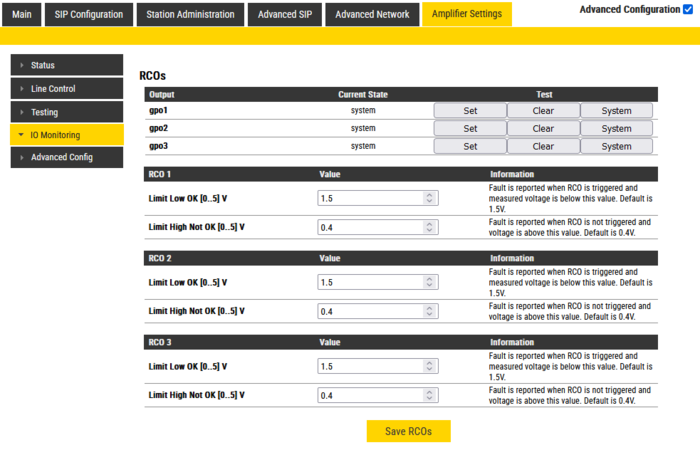
RCOs
The RCOs monitoring alerts when the voltage on the contacts of an output is outside the configured legal value.
- Limit Low OK - If the RCO triggers and the voltage is below this value, it is reported as "Shorted".
- Limit High Not OK - If the RCO is not above this voltage when output is high, it is reported as an "Overload".
The RCOs can be tested from this page. They can be set and cleared. Remember to set them back to System before ending the test.
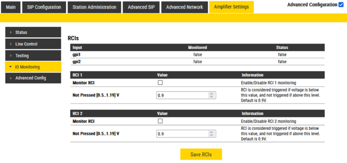
RCIs
The inputs can be used in a conventional way (On/Off), or they can be monitored for Open/Short. A resistor network is needed to enable monitoring of the input.
]
- Monitor RCI enables monitoring of RCI.
- Not Pressed - Lower voltage threshold for the RCI to be considered not activated. No need to change this value if using the recommended resistor values.
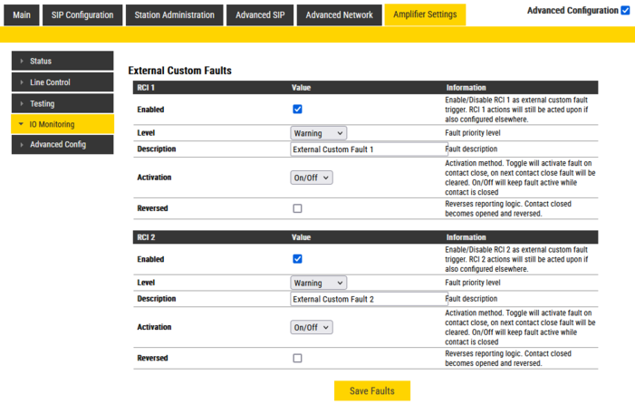
External Custom Faults
A fault signal (closed contact) from an external system/device can be connected to one of the inputs of the amplifier. The amplifier can be configured to report on SNMP trap when the input is triggered. One can add a customized text to be included in the report.
- Enabled: Enable/Disable the input as "external custom fault trigger". When activated an SNMP Trap will be generated. Input actions will still be acted upon if also configured in the GPI Settings.
- Level: Fault priority level
- Description: Fault description. The text will be present in the SNMP trap.
- Activation: Activation method. Toggle will activate fault on contact close, on next contact close fault will be cleared. On/Off will keep fault active while contact is closed
- Reversed: Reverses reporting logic. Contact closed becomes opened and reversed.

|
The SNMP trap Custom Fault must be enabled |
Advanced Config
Enable and configure various monitoring features.
- Power Sources Monitoring
- Monitor AC Power enable AC power monitoring (or Monitor DC power on ENA2060 amplifier)
- Ethernet Switch Port Monitoring
- Monitor Eth 1 monitor Ethernet switch port 1 cable connection
- Monitor Eth 2 monitor Ethernet switch port 2 cable connection


