Adding additional relay(s) to a Zenitel IP Device
From Zenitel Wiki
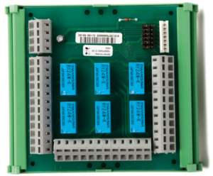
Most Zenitel IP Stations and Devices are equipped with 6 I/O's which, when set as outputs, can be used together with the conventional Multi Relay Board (MRBD) to give up to 6 additional relay contacts.
The relays on the MRBD are double pole, double throw (DPDT) contacts.
Requirements
- Hardware: The Turbine station must be produced week 37 of 2012 or later.
- Software: The Turbine Station must have sw version TCIS-3.0.3.3 or newer.
MRBD Jumper Settings
The MRBD has 6 jumpers (S1-S6) which determines if the relay should be triggered on active "high" signal or active "low" signal. When used with a Zenitel IP Device, the associated jumper must be set to "TouchLine" as indicated in the drawing below.
Connection
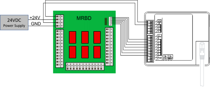
The MRBD must be powered by an external 24VDC power supply.
The same power supply must be connected also to the Zenitel IP device, regardless if it is powered by PoE or not.
Connect the power and I/Os according to the below drawing:
See Turbine Compact series board connectors for more details on Turbine Compact connections.
Device Web configuration
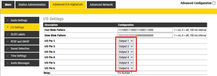
The Zenitel Device must be configured to register to the ICX-AlphaCom in the standard way. In addition the I/O's used with the MRBD must be set to Outputs.
Log on to the Device and navigate to Advanced AlphaCom -> I/O Settings.
Set the I/O('s) that are connected to the MRBD as Output.
AlphaPro configuration
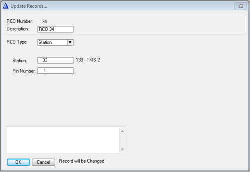
The outputs of the Zenitel Device must be mapped to logical RCO's (Remote Control Output). This is done from AlphaPro. In Exchange & System -> RCO select a free RCO.
- RCO Type: Change to Station.
- Station: Enter the physical number of the Zenitel Device
- Pin Number: Enter the output (1-6) to be related to that logical RCO
The logical RCO's are controlled from the Event Handler.
Configuration examples:


