Getting Started (Zenitel Connect Pro)
From Zenitel Wiki
This article describes step by step how to set up the Zenitel Connect Pro system from the start. It is recommended to follow this article from top down.
The Zenitel Connect Pro is delivered in two ways:
- Installed on dedicated ICX-510 hardware, or
- as an OVA-image which can be installed as a Virtual Machine. OVA images are available for VMWare and VirtualBox, and include the Linux Ubuntu Server 22.04 operating system.
This article is valid for both types of installations.
Prerequisites
Software requirements
- Zenitel Intercom stations and devices: Version 8.1.3.1 or later
License requirements
The Zenitel Connect Pro is a licensed product, and for stations and devices to register to the server, a valid license must be installed.
However, after a factory reset the Zenitel Connect Pro operates fully with a 20 days free license period. The system can be fully configured and tested during the free license period. Just make sure to install a valid license before the free period expires.
For more details regarding licensing, see Licensing in Zenitel Connect Pro
Configuring the Zenitel Connect Pro Server
How to Access the Zenitel Connect Pro web interface
ICX-510: Connect your laptop to Ethernet port 0 (Eth 0) of the ICX-510 unit. Open a web browser (e.g. Chrome or Firefox), and enter the IP address of the ICX-510 in the address bar. The default IP address is 169.254.1.5, with subnet mask 255.255.0.0. Default username and password: admin/admin. Make sure your laptop is in the 169.254.x.x range.
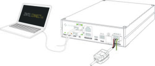 |
| Connect the laptop to the Eth0 port |
Zenitel Connect Pro on Virtual Server: Use the IP address displayed when starting up the virtual machine. Approx. 30 seconds after startup, the IP address is displayed for 120 seconds.
 |
| IP address displayed in virtual environment |
The Zenitel Connect Pro web interface
The web interface consists of four Main Sections:
- System
- Devices and Connections
- Features
- Applications
Each Main Section has a set of menus that can be accesses either by clicking on the Tile, or by selecting from the menu in the Side bar. You can always return to this page by pressing in the top left corner.
Here is a link to a detailed description of each tile.
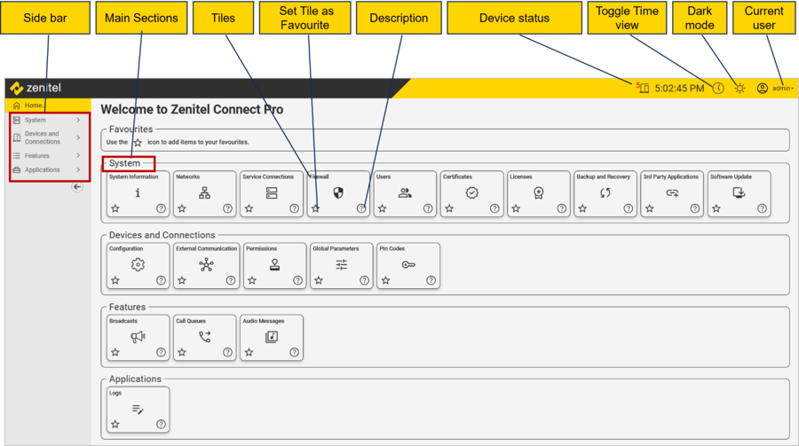 |
| The Homepage of Zenitel Connect Pro |
Software Upgrade
It is highly recommended to upgrade the Zenitel Connect Pro to the latest software version before proceeding with the commissioning.
Download the .swu file from the Downloads section of ZenitelWiki. Go to System > Software Upgrade, and “drag & drop” the file to the area shown below:
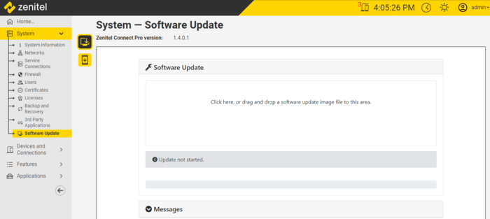 |
| Easy Drag & Drop software update |
The upgrade progress is shown in the web interface. The system will be out of service while the new software is being installed.
Network Settings
The ICX-510 unit has 2 network interfaces, labeled Eth0 and Eth1. The default configuration is:
- Eth0: Static IP-address 169.254.1.5/16
- Eth1: DHCP
Good practice is to use Eth1 for Production (intercom devices, integrations etc.), and keep the default settings on Eth0 and use this interface as a management interface.
A Virtual Machine has a minimum of one network interface. All interfaces are configured as DHCP.
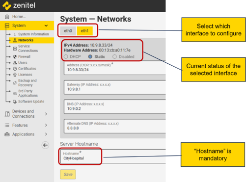 |
| Network configuration |
A "Hostname" is mandatory, and is common for both (all) ethernet interfaces.
The IP addresses are given in CIDR notation.
See Network configuration for more details.
Time Settings
The system time can be synchronized to an external NTP server. If no NTP server available, the time can be manually set. When timezone is set, Daylight Savings Time will auto-adjust.
By clicking on "Map", you can select your timezone from a map:
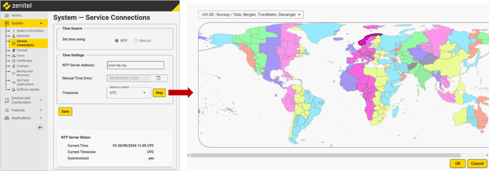 |
| Time Settings |
See Time Settings in Zenitel Connect Pro for more details.
Firewall
The firewall allows inbound rules to be set. Rules can be set for each network interface individually. The system is fully operational with the default Firewall settings.
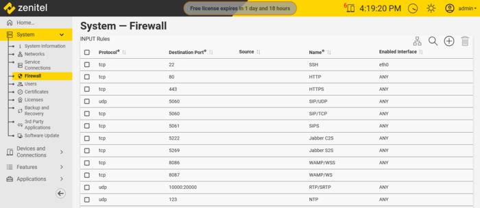 |
| Firewall Settings - Default rules |
Managing rules:
- Add a rule: Click on
on the right hand top side and edit the new line as appropriate
- Edit a rule: Click on
at the end of each rule; edit the rule as appropriate
- Delete a rule: Select or multi-select the rules to be deleted; click on
on the right hand top side of the inbound rules table
Source:
- If left empty, there is no filtering based on the IP-address of the source
- If assigned a subnet address in CIDR notation; example: 192.168.0.0/24, it will only allow traffic from IP-addresses in the range 192.168.0.1 - 192.168.0.254
- If assigned a specific IP-address; only traffic originating from that IP-address is allowed
See Firewall in Zenitel Connect Pro for more details.
Licenses
The Zenitel Connect Pro is a licensed product, and for stations and devices to register to the server, a valid license must be installed.
However, after a factory reset the Zenitel Connect Pro operates fully with a 20 days free license period. The system can be fully configured and tested during the free license period. The remaining time is shown in the top banner of the web interface. Just make sure to install a valid license before the free period expires, else the system will cease to operate.
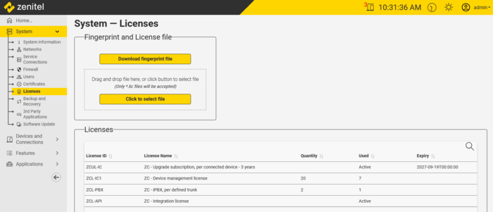 |
| Zenitel Connect Pro - License management page |
See Licensing in Zenitel Connect Pro for more details.
User Management
The default user has Administrator rights with username and password admin/admin.

|
It is strongly recommended to change the password of the default user immediately after the system has been powered on for the first time. |
Any number of users can be defined. There are three roles:
- Administrator – Access to all menus in the web interface. No access to the API via “Zenitel Link”. Administrator can create and delete users.
- Device and Feature Configuration - Access to the Main Sections “Devices and Connections”, “Features” and “Applications”. No access to the “System” section.
- Zenitel Link User - Access to the API via “Zenitel Link”. No access to the web interface.
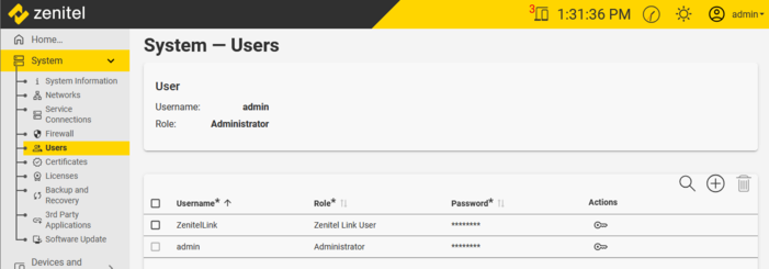 |
| The Users administration page |
Changing a password:
Administrators can change the password for any user. Users with other roles can only change their own password.
- Click on
in the column Actions
- In the new window enter the old and the new password
- Click Change password
Adding users:
A user with the administrator role can define a new user; click to add a new user. A user is defined by entering the following fields:
- Username
- An optional Display Name
- Role
- Password
See User management for more details.
Adding Stations and Devices

|
Zenitel native stations and devices are automatically discovered by and configured from Zenitel Connect Pro. There is no need to log on to the individual devices. |
Prerequisites:
- Device firmware 8.1.3.1 or later
- Devices are Factory Default
- The devices are connected to a network with DHCP server. If the devices are to use Static IP Address, see Adding Devices with Static IP Address
Scan the network for devices
When devices are connected to the network the Zenitel Connect Pro can scan the network and discover the devices, and you can then assign properties, such as number and name, as explained below:
- Connect the devices to the network
- From Zenitel Connect Pro web interface, Devices and Connections > Configuration, run the Scan function
to discover the devices
- From the list of discovered devices, you can identify the device either from its MAC address or by playing a tone in the speaker of the device by clicking the icon
. Playing a tone only works with native Zenitel devices.
- Select Click to assign, and either enter a Directory Number and Name for the device. Or if the device has already been Added Manually, you can select it from the "already added numbers" drop-down list.
- The Zenitel Connect Pro will now push configuration out to the device, the device will register to the server, and should get the configuration status "Configured" in the web interface. The device is now operational.
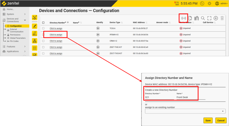 |
| Click to assign a directory number and name to a newly discovered device |
By default the server will scan the subnet(s) defined on the ethernet port(s). Additional subnets can be defined by pressing the icon.
Manually Adding devices
If devices are not yet connected to the network one can manually add the devices either from the Zenitel Connect Pro web interface, or by importing from an Excel spreadsheet. At a later stage, when the devices are connected, perform a Scan, and then pair the discovered physical devices with the manually added devices.
Procedure:
- 1. In the Zenitel Connect Pro web interface select Devices and Connections -> Configuration, select the icon
to add a new device. Enter Directory Number and Name as a minimum. Device Type, MAC Address and Location are optional fields.
- Alternatively, one can import devices from an Excel spreadsheet.
 |
| Manually Adding a device |
- 2. Later, when the devices are connected to the network, run the Scan function
to discover the physical devices
- 3. The next step depends on if the MAC address was included in the first step or not:
- 3.1. If the MAC Address was added in step 1, and there is a match with a MAC of a discovered device, this device will automatically be assigned and become operational
- 3.2. If the MAC address was not added or no match found, you need to assign the physical device to a manually added device by selecting Click to assign and under assign to an existing number select the device from the drop-down list. Devices that are already assigned will be shown in bold text, unassigned devices in non-bold text.
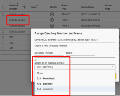 |
| Assigning a discovered device to an already existing number |
Device Status
The Configuration Status for each device is displayed in the Device and Connections > Configuration.
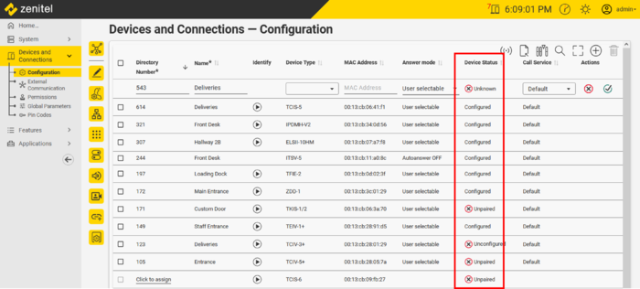 |
| Device status |
The different configuration and operational statuses are:
- Unpaired: The device has not yet been enrolled and/or has not yet received its configuration
- Enrolling: The device has been discovered during the 'Scan'-process, and is now receiving its initial configuration
- Configured: The device has been configured and is fully operational
- Unconfigured: A configuration change made in Zenitel Connect was not sent to the device (yet). This should rectify itself within a few minutes. If it does not rectify itself quickly enough, make a configuration change to the same device (replace some data in a field with the same data) and press Save.
- Offline: The device has been discovered and enrolled, but is no longer registered with the Zenitel Connect server.
Device Password: The devices are automatically assigned a new password by Connect Pro. Click the “eye” to reveal the password. You will be prompted for the Administrator password.
Basic Configuration - Stations
Device Configuration overview
Devices are configured by going to Devices and Connections > Configuration, and selecting a device from the device list (click on the check box to the left), then click one of the configuration icons. It is possible to multi-select devices; then common parameters for the selected devices will be shown.
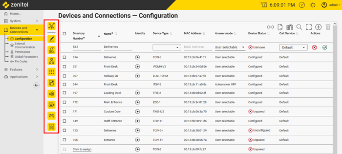 |
| Configuration Icons are located to left in the Device List |
Functions and features behind each configuration icon:
| Configuration Icons |
Call Buttons
Call buttons or DAKs (Direct Access Keys) are configured in the following way:
- In the Zenitel Connect Pro web interface, navigate to Devices and Connections -> Configuration
- Select the device with the Call button you want to configure
- Click on the icon labeled Buttons
- Enter the number to call in Dial String
- In Functions In Call State select what should happen when the button is pressed during the call
 |
| Call button on station 123 configured to call number 677 |
See Call and Function buttons for more details.
OLED Display
If the station is equipped with an OLED display, the display can be configured by selecting the Display Settings configuration icon:
- Click on the icon labeled Display Settings
- Enter parameters as required:
- OLED Brightness: Extra Dim, Dim, Default, Bright, Extra Bright, Max Brightness
- Start Scrolling Time: Time in minutes after which horizontal scrolling should start
- Menu Text Color: Select between Light Text on dark background, or Dark Text on light background (Inverse video).
- Display Text: The text in the display(s)
- Font Size: The font size can be either 12 or 16
 |
| Configuration of the OLED display of an TCIS-5 unit |
Call List (Address Book)
If the station is equipped with an OLED display and buttons for scrolling a Call List/Address Book, the OLED display can be configured by selecting the Display Settings configuration icon:
- Select the station from the device list, and click on the icon labeled Display Settings
- Enter parameters as required:
- OLED Brightness: Extra Dim, Dim, Default, Bright, Extra Bright, Max Brightness
- Start Scrolling Time: Time in minutes after which horizontal scrolling should start
- Menu Text Color: Select between Light Text on dark background, or Dark Text on light background (Inverse video).
- Display Text: The text in the display in idle
- Font Size: The font size can be either 12 or 16
- Sort Call List: Sets how the call list is sorted:
- Off - As configured in the web interface
- Name ascending
- Name descending
- Directory number ascending
- Directory number descending
- Show Directory Number: When enabled the directory number will be shown in square brackets after the name when scrolling through the address book:

 |
| Configuration of the OLED display of a TCIS-6 unit |
The actual Call List / Address Book is configured by selecting the Buttons configuration icon.
- Select the station from the device list, and click on the Buttons icon labeled
- Click the + in the Call List section to add an entry
- Dial String: The number to dial
- Label: The text shown in the OLED display when scrolling to that entry
- Add a new entry below a specific entry by clicking the + (Max 50 entries)
- Change the place of an entry in the Call List by means of the Up or Down arrows, or select "Sort Call List" under the the Display Settings configuration
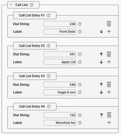 |
| Call List entries |
Audio Settings
From the Audio Settings page one can set loudspeaker volume, enable various audio signal processing features and more.
- Select the station from the device list, and click on the icon labeled Audio
- There are four separate sections:
- Audio Outputs - Set the output gain for the different loudspeaker and line types which the device supports
- Audio Inputs - Set the gain for the different microphone types which the device supports
- Audio Lines - Contains Audio Signal Processing features, used to enhance the audio experience, especially when an intercom is located in an acoustically challenging environment
- AVC (Automatic Volume Control) - The AVC feature automatically adjusts the volume of the loudspeaker to compensate for ambient noise
 |
| Audio Configuration |
Video Settings
If the station is equipped with a camera (e.g. TCIV+, TMIV+ or TEIV+), the default video settings can be modified by selecting the Video configuration icon:
- Select the station from the device list, and click on the icon labeled Video
- For the video streams RTSP H.264 and SIP H.264 the following parameters are adjustable: Resolution, Frames per Second, Bitrate and GOV Length
- For video stream using HTTP MJPEG authentication can be enabled
- Brightness, Saturation and Contrast can be modified
- Zoom and vertical and horizontal Offset can be adjusted, and the image can be Rotated in steps of 90 degrees.
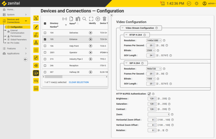 |
| Video Settings |
See Video Configuration for more details.
Answer Mode
The Answer Mode determines if Incoming calls should be ringing, or connect straight through.
Configuration is from Devices and Connections > Configuration; select the device to configure and click the Call Settings icon :
 |
| Answer Mode settings |
- Autoanswer ON: (OPEN mode) Incoming calls will connect straight through, without user having to accept the call
- Autoanswer OFF: (PRIVATE mode) Incoming calls are ringing; users need to accept the call with handset or answer button (e.g. M-key)
- User Selectable: The user can – via display menu – select if the station should use Autoanswer ON or OFF.
See Auto-Answer for more details.
Features
Call Forwarding
There are three types of Call Forwardings available:
- Forwarding on timeout
- Forwarding on busy
- Unconditional forwarding
Set Call Forwarding from the Zenitel Connect Pro web interface:
The configuration is from Devices and Connections > Configuration; select the device to configure and click the Call Settings icon :
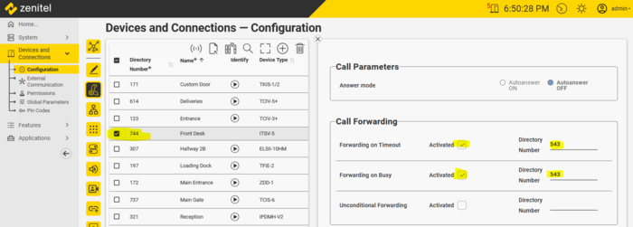 |
| Example: Calls to 744 (Front Desk) are forwarded to 543 if 744 is busy, or if 744 doesn't answer within a preset time |
The timeout before forwarding is configured in Devices and Connections > Global Parameters.
Set Call Forwarding from a station/user:
Call Forwarding is set/reset by dialing the appropriate code. Examples:
*61*543# - Will activate Forwarding on Timeout to number 543. Cancel the forwarding by #61#, the target number will retain. Reestablish the forwarding by *61#.
*67*543# - Will activate Forwarding on Busy to number 543. Cancel the forwarding by #67#, the target number will retain. Reestablish the forwarding by *67#.
*21*543# - Will activate Unconditional Forwarding to number 543. Cancel the forwarding by #21#, the target number will retain. Reestablish the forwarding by *21#.
On Zenitel devices the dial sequence must be pre-configured on a function (DAK) key:
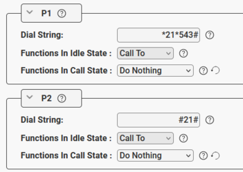 |
| Set and Reset Unconditional Call Forwarding from a DAK key. |
On ITSV Video phones dial the sequence from the keypad, or enter the sequence as a Speed Dial key for single touch activation.
The Zenitel Connect Pro web interface reflects the forwarding status for each device, also when set from the device.
See Call Forwarding for more details.
Door Opening
By pressing digit “6” during a call between an operator and a door intercom, a relay can be operated to trigger the door lock. The relay will be pulsed for 3 seconds.
The configuration is from Devices and Connections > Configuration; select the door intercom and click the Call Settings icon .
Trigger the built-in relay of the door intercom
 |
| Door Opening triggered by digit "6" |
Under the "Door Opening" section set:
- Door Opening Device = “Own Device”
- Door Opening Output = Relay 1 (Optionally "Relay 2" if available, or one of the additional Outputs available on the door intercom)
 |
| Configuration of the Door Opening feature |
Trigger a remote relay located in a safe area
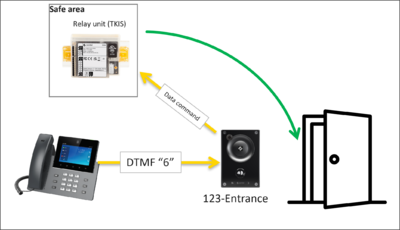 |
| Relay located in safe area |
For security reasons it might be required to operate a relay on a device located in a safe area, instead of controlling the relay of the door intercom itself.
Under the "Door Opening" section set:
- Door Opening Device = Select the remote device from the drop-down list
- Door Opening Output = Relay 1 (Optionally "Relay 2" if available, or one of the additional Outputs available on the door intercom)
 |
| Remote relay in safe area |
Permissions
Door Opening is by default prohibited. Permission must be granted using Call Services.
1. Go to Devices and Connections > Permissions
2. Copy the Default Call Service by selecting the copy icon:
 |
| Copying the Default Call Service by selecting the copy icon |
3. Give the new Call Service a proper name, e.g. "DoorOpeners"
 |
| Giving the new Call Service a proper name |
4. Select the newly created Call Service, and press the (+) icon to add the operation Door Open Callee:
 |
| Adding the operation Door Open Callee |
If you need to restrict door opening to specific door(s), one can add a door intercom number range in the Related to fields. The door opening function will then only be possible towards door intercoms within that range.

|
To allow for Door Opening when the operator calls to the door, add the operation Door Open Caller in addition |
5. Finally, one need to assign the new Call Service to those stations that should be able to activate door opening.
In Devices and Connections > Configuration; select the operator intercom, click the Edit icon, and change the Call Service:
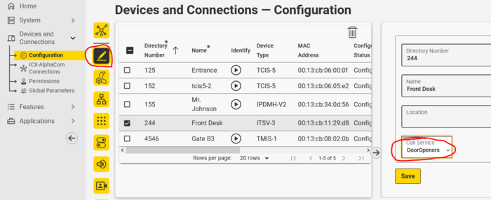 |
| Changing the Call Service |
See Call Services and Permissions for more details.
Call Queuing
Call Queuing is often used in security related communications. Call Queuing has a some advantages versus direct calling:
- 250 priority levels. Call Queues can have different priorities. The highest priority call will always be at the top of the Call Queue. 250 priority levels.
- A call to a Call Queue is always indicated by ringing in the Operator device, regardless of the auto-answer setting.
- Parallel call: Several operators can be called in parallel
- Sequential call: A call can be escalated to next level (a new Call Queue or individual operator) if the original call is not attended to within a preset time
- Individual timeout per queue
Call Queues are configured from Features > Call Queues:
- Press (+) to add a new queue
- Enter a Directory Number, Name and Queue Timeout
- Add operator(s) to the queue
Example: Dialing 6701 should place a call to 678 (Reception) and 244 (Front Desk) in parallel. If not answered withing 25 seconds, the call should be forwarded to 543 (Main Guard):
 |
| Call 678 and 244 in parallel. If not answered withing 25 seconds, the call will be forwarded to 543 (Main Guard) |
Call Queue configuration:
 |
| Call 678 and 244 in parallel. If not answered withing 25 seconds, the call will be forwarded to 543 (Main Guard) |
Broadcast
The broadcast feature is used for distribution of live audio announcements to a group of devices. An announcement will be preceded with a chime signal.
- Up to 10 broadcast groups are supported
- Priority levels 1 to 250, 70 is default
- If a device is receiving two or more group calls at the same time:
- The highest priority group will be played
- If equal priority, the first one will be played
- Priority 1- 20 (Emergency): Volume & Handset override
- Configurable timeout (default =3600 sec.)
- Permission to start a broadcast can be restricted in Devices and Connections > Permissions
Broadcast groups are created and configured from Features > Broadcasts:
- Press (+) to add a new group
- Enter a Directory Number and Name
- Add members to the group
Example: Dialing 85 should activate a live announcement to 613 (Deliveries) and 4545 (Corridor 2A):
 |
| 85 is activating a live announcement to 613 (Deliveries) and 4545 (Corridor 2A) |
Broadcast configuration:
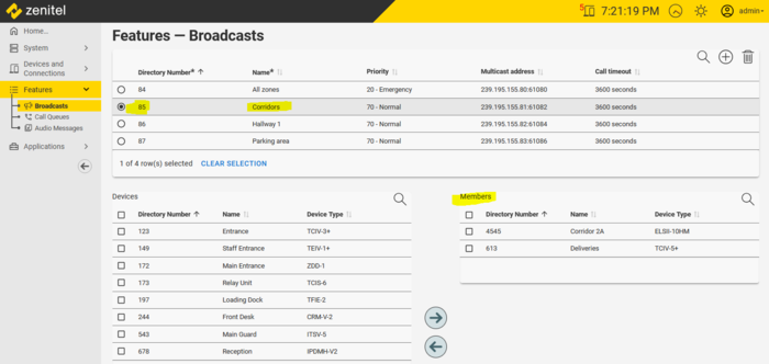 |
| 85 is activating a live announcement to 613 (Deliveries) and 4545 (Corridor 2A) |
Inputs
Most Zenitel Devices have GPIOs (General Purpose Inputs/Outputs).
Inputs are configured in the following way:
- In the Zenitel Connect Pro web interface, navigate to Devices and Connections -> Configuration
- Select the device you want to configure
- Click on the icon labeled Inputs & Outputs
, and select the input to configure
- Enter the number to call in Dial String
- In Functions In Call State select what should happen when the input is activated during the call
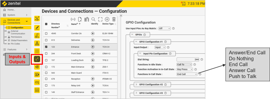 |
| Input #1 on station 123 configured to call number 244 |
Relays
Most Zenitel Devices have one or two built-in relays.
The relay configuration is done from Devices and Connections > Configuration:
- Select the device you want to configure
- Click on the icon labeled Inputs & Outputs
, and scroll down to Output Configuration #1
- Select which call events should operate the relay
- The actions to select from are:
- Do Nothing
- On
- Off
- Slow Flash
- Fast Flash
Slow Flash has a pattern of 1.2 sec On/1.2 sec Off
Fast Flash has a pattern of 0.3 sec On/0.3 sec Off
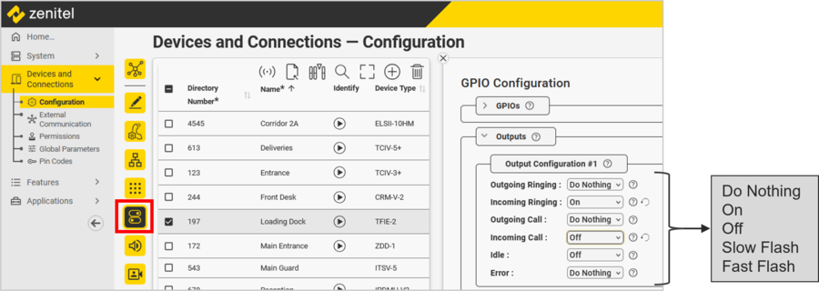 |
| Relay #1 on station 197 configured for Call Indication |
Outputs
Most Zenitel Devices have GPIOs (General Purpose Inputs/Outputs).
The output configuration is done from Devices and Connections > Configuration:
- Select the device you want to configure
- Click on the icon labeled Inputs & Outputs
, and select the GPIO to configure
- Set the Input/Output = Output
- Select which call events should operate the output
- The actions to select from are:
- Do Nothing
- On
- Off
- Slow Flash
- Fast Flash
Slow Flash has a pattern of 1.2 sec On/1.2 sec Off
Fast Flash has a pattern of 0.3 sec On/0.3 sec Off
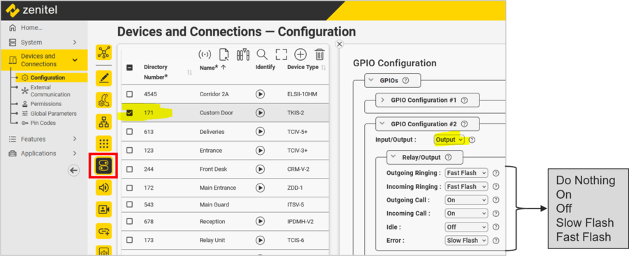 |
| Output #2 on station 171 configured to operate a Call LED |
