Difference between revisions of "AlphaCom XE7"
From Zenitel Wiki
(→Remote Control Outputs (RCO)) |
(→Remote Control Outputs (RCO)) |
||
| Line 99: | Line 99: | ||
<br style="clear:both;" /> | <br style="clear:both;" /> | ||
| − | The operation of the outputs are configured in the [[Event Handler]]. By default the outputs from the XE7 server are mapped to logical RCO number 1 - 12, and | + | The operation of the outputs are configured in the [[Event Handler]]. By default the outputs from the XE7 server are mapped to logical RCO number 1 - 12, and are controlled by the [[RCO - Set Remote Control Output|RCO command]]. |
| + | Here are some examples: | ||
| + | * [[1-4h. Door Opening, Code Lock (practice)|Door opening and Code lock]] | ||
| + | * [[2-2a. Call indication - Event Handler (practice)|Call indication]] | ||
====Mapping==== | ====Mapping==== | ||
Revision as of 14:11, 4 March 2019
Contents
Highlights
- Made to provide critical communication in any environment
- Supports 552 stations, of which 36 stations can be analog intercom stations
- SIM card based software configuration and disaster recovery
- Fully compatible with any AlphaCom system
Mounting & Dimensions
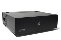
The XE7 cabinet can be wall or shelf mounted, or mounted in a 19” rack. It has room for installation of one AMC-IP processor board and up to 6 feature boards. The server includes a power board and a cooling fan.
Installation
- Remove the front cover of the XE7 cabinet
- Prepare the AMC-IP board with the STIC according to this article, then insert the AMC-IP board into board position 7.

|
|
- Insert the remaining feature boards (ASLT, ATLB-12 or AGA boards) in position 1 to 6. Normally you would start from board position 1 and upwards.
- Power up the XE7 server by connecting the output from the 24VAC transformer to the "24VAC In" connector.
- Alternatively connect a 24VDC power source to the "24VDC In" connector.
- Watch the LEDs of the AMC-IP board. The system uses approx. 70 seconds to start up. When running the green status LED of the AMC-IP board should be flashing.
- Connect a laptop to Eth 0 port, open a web browser (e.g. Firefox or Chrome), and log on to the embedded web server using IP address 169.254.1.5. (Default Username/Password = admin/alphaadmin)
- Upgrade the software of the server to the latest version. Upgrade is done from the web interface of the server. This will ensure that the system has the latest features, bug fixes and security updates.
- Replace the front cover of the XE7 cabinet
Configuration
- AlphaPro is the Windows application used for configuring the AlphaCom XE system. Configuration of user data, such as Directory Numbers, Direct Access Keys, Group Calls etc. is done from AlphaPro.
- AlphaWeb is the embedded web server running on AlphaCom XE. The AlphaWeb server provides functions for system monitoring, system configuration, and system upgrade. Initial connection is done by connecting a laptop to Eth 0 port, open a web broswer (e.g. Firefox or Chrome), and log on to the web server using IP address 169.254.1.5. (Default Username/Password = admin/alphaadmin).
Connection details
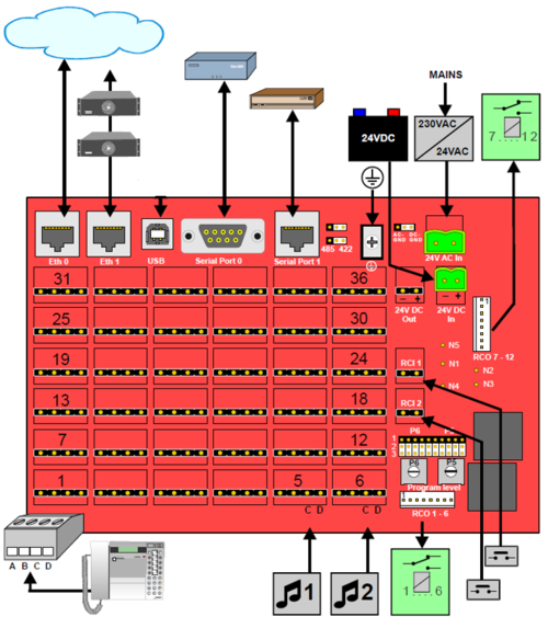
Power
The server is normally powered from the mains via a 24VAC transformer. Battery backup power can be connected to the 24VDC input plug.
Network
The XE7 server has two RJ-45 ethernet ports for IP communication. Ethernet port 0 (Eth 0) is by default configured as a Management port, allowing connection to the embedded web server (AlphaWeb) and connection of the PC configuration tool AlphaPro. Default IP addresses:
- Eth0 has IP address 169.254.1.5
- Eth1 gets IP address from DHCP by default
Analogue Intercom Stations
There are 36 physical ports for analog stations on the XE7. Station cables are terminated to these physical ports by means of plugable screw connectors on the backplane.
Audio Program Inputs
Physical number 5 and 6 on the first ASLT line board are by default enabled for audio program distribution. If more program inputs are required, one can use the AGA board (6 programs per board), or use the TKIE-2 kit as Audio Program interface.
If you want to use the physical ports 5 & 6 for regular analog stations instead, see article Physical number 5 and 6 (AlphaCom E7)
Serial Ports
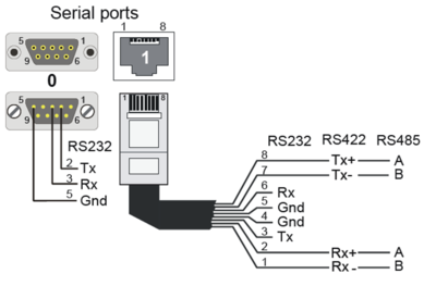
Serial ports can be used for communication with external equipment. There are two serial ports:
- Serial Port 0: R232 on an 9-Pin D-sub connector
- Serial Port 1: RS232, RS422 or RS485 on an RJ45 connector:
- RS232:: Switch 8 on S601 on the AMC-IP board must be set to OFF (default).
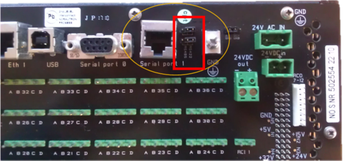
- RS422: Switch 8 on S601 on the AMC-IP board must be set to ON. Jumpers on backplane in RS422 position.
- RS485: Switch 8 on S601 on the AMC-IP board must be set to ON. Jumpers on backplane in RS485 position.
Remote Control Inputs (RCI)
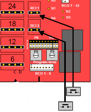
There are two remote control inputs available at the backplane of the XE7 server, called RCI 1 and RCI 2. The inputs are triggered by dry contacts. What actions to trigger when an input is activated is configured from AlphaPro in the RCI table. For more information on usage and configuration, see RCI - Remote Contol Input.
Remote Control Outputs (RCO)
There are 12 Remote Control Outputs (RCO) available from the XE7 server.
- RCO 1 to 6 are operated by the ASLT or ATLB-12 board in board postion 1
- RCO 7 to 12 are operated by the ASLT or ATLB-12 board in board postion 2
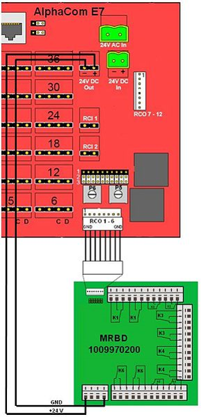
The outputs are designed to drive the relays on a MRBD relay board.

|
When the ATLB-12 board is used, there will be only four RCOs available (not six) |
Connection of MRBD Relay Board:
The operation of the outputs are configured in the Event Handler. By default the outputs from the XE7 server are mapped to logical RCO number 1 - 12, and are controlled by the RCO command.
Here are some examples:
Mapping
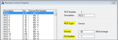
The RCO's in an Alphacom XE7 must be mapped. This is done using AlphaPro. Navigate to Exchange & System -> RCO window where the logical RCO is assigned to a physical address.
The physical address is given as Device + Pin Number
- RCO 1-138 are by default mapped to the internal RCOs in the AlphaCom, i.e. device 65 - pin 1 to device 65 - pin 138. For XE7 it is only the first 12 RCO's which would be default mapped to the correct physical address
- Mapping for all other RCO's must be configured manually
- The RCO's can be used freely within the system, e.g. an event on one station can operate an RCO located on a different station or device.
- The exchange always keeps track of the state of an output in case the device becomes faulty. When a faulty device becomes OK again, the exchange will restore the current RCO state.
Factory Reset (coldstart)
Performing a cold start of the AMC-IP board will delete all previous programming, load factory default settings and set the IP-address to 169.254.1.5 with mask 255.255.0.0 on Eth0.
Cold start procedure
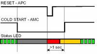
- Press the reset button on the power card briefly while keeping the cold start button pressed.
- Keep the cold start button pressed at least 2 sec. after power on. The AMC status LED will blink green when the boot is ready.
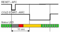
Cold-start of AMC application only, keep IP setting
- Press the reset button on the power card briefly.
- After 10 seconds, press the cold start button on the AMC-IP board.
- Keep the cold start button pressed until the AMC status LED is blinking green.
Modify Factory Default Settings
After cold start the system is set up with a default program and is working without any further programming. To change or add to the default settings, the AlphaPro programming tool must be used.
Other methods of factory default
A factory default can also be achieved in other ways:
- From AlphaWeb: System Maintenance -> System Recovery -> Load Factory Defaults
- From AlphaPro: Upload a default AlphaPro database to the exchange

