IP Substation Kit - 1008090200: Difference between revisions
From Zenitel Wiki
No edit summary |
No edit summary |
||
| Line 1: | Line 1: | ||
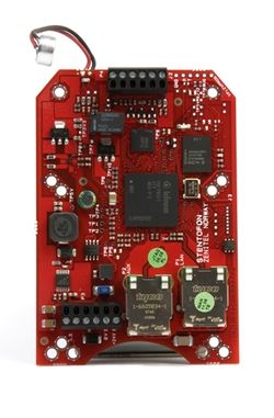
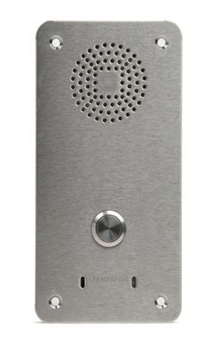
[[Image:80902 RS.jpg|thumb|250px|IP Substation Kit]] | [[Image:80902 RS.jpg|thumb|250px|IP Substation Kit]] | ||
===<u>[[INCA Substation PCB LED Indicators|PCB LED Indications]]</u>=== | ===<u>[[INCA Substation PCB LED Indicators|PCB LED Indications]]</u>=== | ||
Revision as of 20:27, 17 March 2017
PCB LED Indications
Dimensions
Reset to factory settings
Board Connectors
Additional Documentation on Zenitel.com
Related Articles
- IP Substation - Amplified calling
- Mounting and Assembly Kit for IP Substation - 1008091000
- IP SubStations, Acoustical design
- IP Station License
Connections
Configuration
The station can operate in three different modes, depending on what kind of server the station should register to. Choose one of the links below according to what mode you need to configure.
- IP Station Configuration - AlphaCom mode
- IP Station Configuration - SIP mode
- IP Station Configuration - Pulse mode


