Difference between revisions of "AlphaCom XE20"
From Zenitel Wiki
(→Specifications) |
(→Cold start procedure) |
||
| (42 intermediate revisions by 3 users not shown) | |||
| Line 1: | Line 1: | ||
| − | [[Image:XE20.PNG|thumb| | + | [[Image:XE20.PNG|thumb|350px|AlphaCom XE20 Audio Server with HD Voice]] |
| − | + | =Highlights= | |
| + | * Made to provide critical communication in any environment | ||
| + | * Supports 552 IP stations and 102 analog intercom stations | ||
| + | * SIM card based software configuration and disaster recovery | ||
| + | * Fully compatible with any AlphaCom system | ||
| − | = | + | =Mounting & Dimensions= |
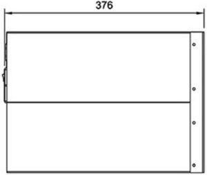
| − | + | The cabinet is intended for mounting in a 19” rack. It has room for installation of 20 circuit boards in total: one AMC-IP processor board, one APC program & clock board, and up to 18 feature boards. The server also includes a mains power supply. | |
| − | == | + | [[File:XE20FrontView.PNG|300px|left|thumb|Front View]] |
| − | * | + | <br style="clear:both;" /> |
| − | + | [[File:XE20RearView.PNG|300px|left|thumb|Rear View]] | |
| − | + | <br style="clear:both;" /> | |
| − | + | [[File:XE20TopView.png|300px|left|thumb|Top View]] | |
| − | + | <br style="clear:both;" /> | |
| − | + | [[File:XE20SideView.PNG|300px|left|thumb|Side View]] | |
| − | + | <br style="clear:both;" /> | |
| − | * | + | |
| − | + | =Installation= | |
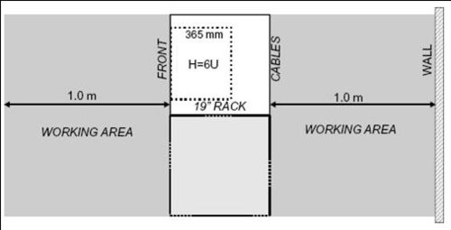
| − | + | * Up to 4 units may be mounted in one 19” rack if sufficient ventilation is provided. It is recommended to mount a cooling fan module on top of each exchange unit. | |
| − | * | + | [[image:AC E20 Installation.jpg|thumb|500px|left|Mounting AlphaCom XE20]] |
| − | * | + | <br style="clear:both;" /> |
| + | |||
| + | =Board positions= | ||
| + | [[Image:XE20 backplane2.png|thumb|500px|left|Board positions and physical numbers in AlphaCom XE20]] | ||
| + | <br style="clear:both;" /> | ||
| + | |||
| + | =Connections= | ||
| + | [[File:XE20 Connections.PNG|thumb|left|500px]] | ||
| + | <br style="clear:both;" /> | ||
| + | |||
| + | ===Power=== | ||
| + | The AlphaCom XE comes with one integrated [[APWR Power supply|power supply 1009703000]]. The power supply is supplied from the mains (100 - 240VAC). | ||
| + | |||
| + | ===Network=== | ||
| + | Two RJ-45 Ethernet terminals on the [[Filter card AMC-IP|IP filter board]] are used for IP LAN and WAN communication | ||
| + | |||
| + | ===Analogue Intercom Stations=== | ||
| + | The two-pair star wired intercom cables are connected to connection boards on the cabinet DIN rail or in a separate distribution field | ||
| + | |||
| + | ===Program Input=== | ||
| + | 6 [[Audio Program|program distribution]] sources can be connected to the [[APC - AlphaCom Program & Clock Board|APC board]] via an optional program connection board. Up to 64 extra programs may be added using AGA boards with 16 programs per board | ||
| + | |||
| + | ===Serial Ports=== | ||
| + | The serial ports with RS232 and RS422/RS485 interfaces are used for connecting to equipment using these protocols | ||
| + | |||
| + | [[Image:AMC-IP-Connections.PNG|thumb|left|400px]] | ||
| + | <br style="clear:both;" /> | ||
| + | |||
| + | ====Serial Port 0==== | ||
| + | RJ45 (RS232 Only) | ||
| + | :No additional settings necessary | ||
| + | |||
| + | ====Serial Port 1==== | ||
| + | RJ45 (RS232/422/485) | ||
| + | :Additional settings: | ||
| + | :'''RS232:''' | ||
| + | :* [[AMC-IP_-_AlphaCom_Processor_Board_(Red)#Switches_and_jumpers|Switch 8 on S601]] on the AMC-IP board must be set to OFF. | ||
| + | |||
| + | :'''RS422/485:''' | ||
| + | :* [[AMC-IP_-_AlphaCom_Processor_Board_(Red)#Switches_and_jumpers|Switch 8 on S601]] on the AMC-IP board must be set to ON. | ||
| + | :* Use the two jumpers on the AMC-IP [[Filter card AMC-IP|Filterboard]] to select between RS422 and RS485. | ||
| + | [[File:SerialPortJumpers XE20 26.png|thumb|left|500px|RS422/485 selector for Serial Port 1 on the XE20 AMC-IP Filterboard]] | ||
| + | <br style="clear:both;" /> | ||
| − | == | + | ===Remote Control Inputs (RCI)=== |
| − | [[ | + | ====Connections==== |
| + | The [[Filter card APC|optional program connection]] board has input for 6 Remote Control Inputs ([[RCI]]) which can initiate programmed actions | ||
| + | [[File:RCI XE26.png|left|thumb|500px|right|RCI inputs in an AlphaCom XE20 and XE26]] | ||
<br style="clear:both;" /> | <br style="clear:both;" /> | ||
| − | == | + | ====Configuration==== |
| − | + | In [[AlphaPro]] there is an [[Exchange_%26_System_%28AlphaPro%29#RCI|RCI table]], where the physical address of the input is entered, along with the desired actions. The physical address is given as [[device]] + pin-number. | |
| − | The | + | |
| − | + | The RCI table supports up to 140 inputs. | |
| − | + | * For internal RCIs in the AlphaCom XE20, the device address is 65-68, and the pin number is 1-6. | |
| − | + | * Internal pin number 8 is the [[Temperature Alarm|temperature alarm]] | |
| − | + | * Mappings for the internal RCI's are [[Autoload|autoloaded]]. Mappings for external RCI's (Slave modules, RIO's or IPARIO) must be manually programmed. | |
| − | |||
| − | |||
| − | |||
{| border="1" | {| border="1" | ||
| + | ! style="background:#ffdead;" width="150" | | ||
| + | ! style="background:#ffdead;" width="80" |RCI Type | ||
| + | ! style="background:#ffdead;" width="150" |Device/Station physical Number | ||
| + | ! style="background:#ffdead;" width="100" |Pin Number | ||
|- | |- | ||
| − | | | + | | align=center | AlphaCom XE20 || align=center | Device || align=center | 65-68 || align=center | 1 - 6 |
| − | | | ||
|- | |- | ||
| − | | | + | |} |
| − | + | ||
| − | + | ====Example==== | |
| − | + | <big>Start fire alarm message and activate rotating lamp:</big> | |
| − | + | [[File:RCI Conf Example1.PNG|left|800px]] | |
| − | + | <br style="clear:both;" /> | |
| − | + | ||
| − | + | [[File:RCI Conf Example2.PNG|left|500px]] | |
| − | + | <br style="clear:both;" /> | |
| − | | | + | |
| − | + | AMG 1 3 - Alarm Message 3 (8193) to group 1 (84) | |
| − | + | RCO 5 ON – Turn on the relay that controls the lamp | |
| − | | | + | |
| − | + | AMG 1 0 – Alarm Message OFF to group 1 (84) | |
| − | + | RCO 5 OFF – Turn off the lamp | |
| − | + | ||
| − | + | '''Note:''' Multiple commands are separated by semicolon ( ; ) | |
| − | + | ||
| − | + | ===Remote Control Outputs (RCO)=== | |
| − | + | Each [[ASLT|subscriber line card]] provides 6 freely programmable Remote Control Outputs ([[RCO]]) | |
| − | + | ||
| − | + | {| border="1" | |
| − | + | ! style="background:#ffdead;" width="250" |Device | |
| − | + | ! style="background:#ffdead;" width="50" |# of RCO's | |
| − | + | ! style="background:#ffdead;" width="300" |Comment | |
| − | + | ! style="background:#ffdead;" width="400" |Hardware required | |
| − | |||
| − | |||
| − | |||
| − | |||
| − | |||
| − | |||
| − | |||
| − | |||
| − | |||
| − | |||
| − | |||
| − | |||
| − | |||
| − | |||
| − | |||
| − | |||
| − | |||
| − | |||
| − | |||
| − | |||
| − | |||
| − | |||
| − | |||
| − | |||
| − | |||
| − | | | ||
| − | |||
| − | |||
| − | |||
| − | |||
| − | |||
| − | |||
| − | | | ||
| − | | | ||
| − | |||
| − | |||
| − | |||
| − | | | ||
| − | | | ||
| − | |||
| − | |||
|- | |- | ||
| − | | | + | | align=center | AlphaCom XE20 || align=center | 102|| align=center | 6 RCOs per [[ASLT]] card or [[ATLB-12]] card || align=center | [[MRBD - Relay Board|MRBD relay board]] |
|- | |- | ||
|} | |} | ||
| − | [[ | + | ====Connections==== |
| − | [[Category:AlphaCom | + | Alphacom XE20 RCO’s operate [[MRBD]] relays: |
| + | [[File:RCOinXE20.png|thumb|left|400px]] | ||
| + | <br style="clear:both;" /> | ||
| + | |||
| + | ====Mapping==== | ||
| + | The RCO's in an Alphacom XE20 must be mapped. This is done using AlphaPro. Navigate to Exchange & System -> [[Exchange_%26_System_%28AlphaPro%29#RCO|RCO window]] where the logical RCO is assigned to a physical address. | ||
| + | |||
| + | The physical address is given as '''[[Device]]''' + '''Pin Number''' | ||
| + | |||
| + | [[File:XE7RCOMapping.png|thumb|left|500px]] | ||
| + | <br style="clear:both;" /> | ||
| + | |||
| + | * RCO 1-138 are by default mapped to the internal RCOs in the AlphaCom, i.e. device 65 - pin 1 to device 65 - pin 138. For XE20 the 6 first RCO's are correctly default mapped to the physical address. RCO 7-42 are not physically available, since they are by default mapped to physical number 7-42 which is not available due to the power supply. RCO 43-138 are default mapped to the correct physical address. | ||
| + | * Mapping for all other RCO's must be configured manually | ||
| + | * The RCO's can be used freely within the system, e.g. an event on one station can operate an RCO located on a different station or device. | ||
| + | * The exchange always keeps track of the state of an output in case the device becomes faulty. When a faulty device becomes OK again, the exchange will restore the current RCO state. | ||
| + | |||
| + | =Factory Reset (coldstart)= | ||
| + | Performing a '''cold start''' of the AMC-IP board will delete all previous programming, load factory default settings and set the IP-address to 169.254.1.5 with mask 255.255.0.0 on Eth0. | ||
| + | |||
| + | [[File:AMC-IP ColdStartButton2.png|thumb|left|100px|Cold start button on AMC-IP board]] | ||
| + | <br style="clear:both;" /> | ||
| + | |||
| + | ===Cold start procedure=== | ||
| + | [[Image:Cold Start of AMC-IP.jpg|right|200px|thumb|Cold start to load default factory settings]] | ||
| + | *Press and hold the cold start button on the AMC-IP card | ||
| + | * Press the reset button on the [[APC|APC board]] briefly | ||
| + | *Keep the cold start button pressed at least 2 more seconds. The AMC-IP status LED will blink green when the boot is ready. | ||
| + | <br style="clear:both;" /> | ||
| + | |||
| + | === Cold-start of AMC application only, keep IP setting === | ||
| + | [[Image:Cold Start of AMC-IP.2.jpg|right|200px|thumb|Cold-start of AMC application]] | ||
| + | *Press the reset button on the [[APC|APC board]] briefly. | ||
| + | *After 10 seconds, press the cold start button on the AMC-IP board. | ||
| + | *Keep the cold start button pressed until the AMC status LED is blinking green. | ||
| + | <br style="clear:both;" /> | ||
| + | |||
| + | ===Modify Factory Default Settings=== | ||
| + | After cold start the system is set up with a default program and is working without any further programming. To change or add to the default settings, the [[AlphaPro]] programming tool must be used. | ||
| + | |||
| + | ===Other methods of factory default=== | ||
| + | A factory default can also be achieved in other ways: | ||
| + | * '''From [[AlphaWeb]]''': System Maintenance -> System Recovery -> Load Factory Defaults | ||
| + | * '''From [[AlphaPro]]:''' Upload a default AlphaPro database to the exchange | ||
| + | |||
| + | =Upgrade= | ||
| + | ===Software upgrade=== | ||
| + | See [[AMC-IP software upgrade]] | ||
| + | |||
| + | ===Hardware Upgrade=== | ||
| + | See [[AlphaCom Exchange Upgrade]] | ||
| + | |||
| + | = Additional Documentation on Zenitel.com = | ||
| + | * [http://www.zenitel.com/product/alphacom-xe20 Additional Documentation on Zenitel.com] | ||
| + | [[Category:AlphaCom Servers]] | ||
Latest revision as of 13:24, 24 April 2023
Contents
Highlights
- Made to provide critical communication in any environment
- Supports 552 IP stations and 102 analog intercom stations
- SIM card based software configuration and disaster recovery
- Fully compatible with any AlphaCom system
Mounting & Dimensions
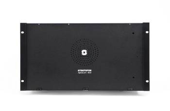
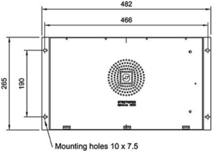
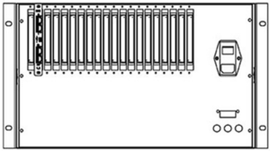
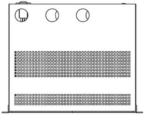
The cabinet is intended for mounting in a 19” rack. It has room for installation of 20 circuit boards in total: one AMC-IP processor board, one APC program & clock board, and up to 18 feature boards. The server also includes a mains power supply.
Installation
- Up to 4 units may be mounted in one 19” rack if sufficient ventilation is provided. It is recommended to mount a cooling fan module on top of each exchange unit.
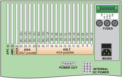
Board positions
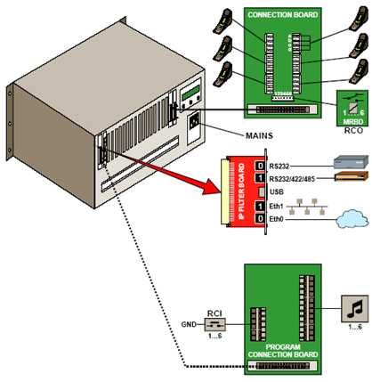
Connections
Power
The AlphaCom XE comes with one integrated power supply 1009703000. The power supply is supplied from the mains (100 - 240VAC).
Network
Two RJ-45 Ethernet terminals on the IP filter board are used for IP LAN and WAN communication
Analogue Intercom Stations
The two-pair star wired intercom cables are connected to connection boards on the cabinet DIN rail or in a separate distribution field
Program Input
6 program distribution sources can be connected to the APC board via an optional program connection board. Up to 64 extra programs may be added using AGA boards with 16 programs per board
Serial Ports
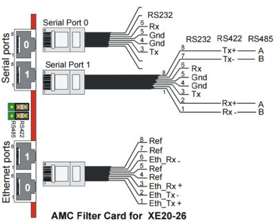
The serial ports with RS232 and RS422/RS485 interfaces are used for connecting to equipment using these protocols
Serial Port 0
RJ45 (RS232 Only)
- No additional settings necessary
Serial Port 1
RJ45 (RS232/422/485)
- Additional settings:
- RS232:
- Switch 8 on S601 on the AMC-IP board must be set to OFF.
- RS422/485:
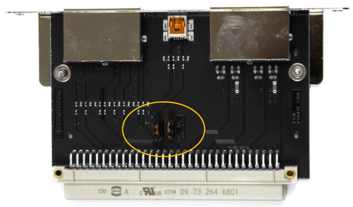
- Switch 8 on S601 on the AMC-IP board must be set to ON.
- Use the two jumpers on the AMC-IP Filterboard to select between RS422 and RS485.
Remote Control Inputs (RCI)
Connections
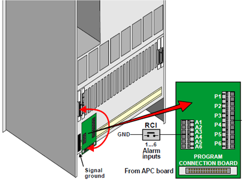
The optional program connection board has input for 6 Remote Control Inputs (RCI) which can initiate programmed actions
Configuration
In AlphaPro there is an RCI table, where the physical address of the input is entered, along with the desired actions. The physical address is given as device + pin-number.
The RCI table supports up to 140 inputs.
- For internal RCIs in the AlphaCom XE20, the device address is 65-68, and the pin number is 1-6.
- Internal pin number 8 is the temperature alarm
- Mappings for the internal RCI's are autoloaded. Mappings for external RCI's (Slave modules, RIO's or IPARIO) must be manually programmed.
| RCI Type | Device/Station physical Number | Pin Number | |
|---|---|---|---|
| AlphaCom XE20 | Device | 65-68 | 1 - 6 |
Example
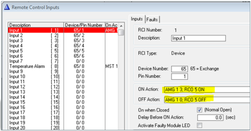
Start fire alarm message and activate rotating lamp:
AMG 1 3 - Alarm Message 3 (8193) to group 1 (84)
RCO 5 ON – Turn on the relay that controls the lamp
AMG 1 0 – Alarm Message OFF to group 1 (84)
RCO 5 OFF – Turn off the lamp
Note: Multiple commands are separated by semicolon ( ; )
Remote Control Outputs (RCO)
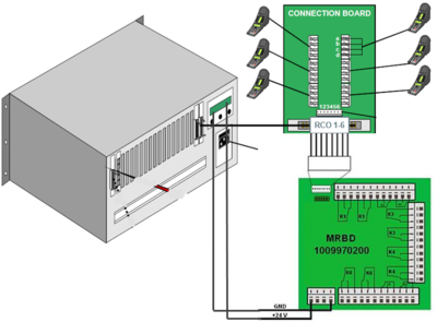
Each subscriber line card provides 6 freely programmable Remote Control Outputs (RCO)
| Device | # of RCO's | Comment | Hardware required |
|---|---|---|---|
| AlphaCom XE20 | 102 | 6 RCOs per ASLT card or ATLB-12 card | MRBD relay board |
Connections
Alphacom XE20 RCO’s operate MRBD relays:
Mapping
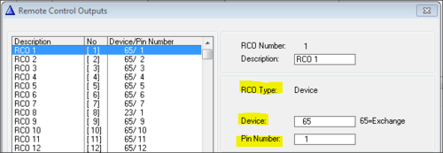
The RCO's in an Alphacom XE20 must be mapped. This is done using AlphaPro. Navigate to Exchange & System -> RCO window where the logical RCO is assigned to a physical address.
The physical address is given as Device + Pin Number
- RCO 1-138 are by default mapped to the internal RCOs in the AlphaCom, i.e. device 65 - pin 1 to device 65 - pin 138. For XE20 the 6 first RCO's are correctly default mapped to the physical address. RCO 7-42 are not physically available, since they are by default mapped to physical number 7-42 which is not available due to the power supply. RCO 43-138 are default mapped to the correct physical address.
- Mapping for all other RCO's must be configured manually
- The RCO's can be used freely within the system, e.g. an event on one station can operate an RCO located on a different station or device.
- The exchange always keeps track of the state of an output in case the device becomes faulty. When a faulty device becomes OK again, the exchange will restore the current RCO state.
Factory Reset (coldstart)
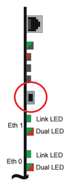
Performing a cold start of the AMC-IP board will delete all previous programming, load factory default settings and set the IP-address to 169.254.1.5 with mask 255.255.0.0 on Eth0.
Cold start procedure
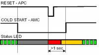
- Press and hold the cold start button on the AMC-IP card
- Press the reset button on the APC board briefly
- Keep the cold start button pressed at least 2 more seconds. The AMC-IP status LED will blink green when the boot is ready.
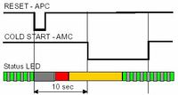
Cold-start of AMC application only, keep IP setting
- Press the reset button on the APC board briefly.
- After 10 seconds, press the cold start button on the AMC-IP board.
- Keep the cold start button pressed until the AMC status LED is blinking green.
Modify Factory Default Settings
After cold start the system is set up with a default program and is working without any further programming. To change or add to the default settings, the AlphaPro programming tool must be used.
Other methods of factory default
A factory default can also be achieved in other ways:
- From AlphaWeb: System Maintenance -> System Recovery -> Load Factory Defaults
- From AlphaPro: Upload a default AlphaPro database to the exchange

