Pulse System Configuration: Difference between revisions
From Zenitel Wiki
No edit summary |
|||
| Line 135: | Line 135: | ||
See [[Audio Messaging (Pulse/SIP)|Audio Messaging]] for more details. | See [[Audio Messaging (Pulse/SIP)|Audio Messaging]] for more details. | ||
=== Button and LED configuration for customized stations [Turbine only]=== | === Button and LED configuration for customized stations [Turbine only]=== | ||
| Line 141: | Line 142: | ||
For more details, see [[Button and LED configuration for customized stations (Pulse/SIP)]] | For more details, see [[Button and LED configuration for customized stations (Pulse/SIP)]] | ||
=== Backup and Restore === | === Backup and Restore === | ||
Revision as of 13:23, 25 February 2019
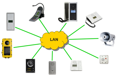
The Pulse system is a SIP intercom system intended for small to mid-size installations for up to 64 IP stations. Up to 16 stations can be used without the need of a license. The Pulse System is easy to install and configure. It can be configured using a standard web browser (like Firefox or Chrome), or one can use the dedicated Intercom Management Tool IMT.
One of the intercom stations must be set as the "Pulse Server". The Pulse Server is acting as a server for the other intercom stations in the system. Any station can be a Pulse Server. However, more features are available if a Turbine station is acting as a Pulse Server. There must be only one Pulse Server in the installation.
This article described step by step how to configure a Pulse System using the Web interface, and all optional configurations and settings available.
Getting Started
Configure the Pulse Server
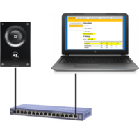
- Decide which station to use as a Pulse Server, and connect that station to a PoE Ethernet switch. Do not connect any other stations at this point.
- Connect your laptop computer to the network switch
- Start a web browser (e.g. Firefox or Chrome), and log on to the station.
- In Main Settings, set "Station Mode" = Use Pulse Server. Enable Static IP, and enter the IP address and network mask of the Pulse Server (Note: Do not use DHCP on the Pulse Server)
- Press Save and Apply. The station will now reboot, and start up as a Pulse Server
Configure the remaining Intercom Stations
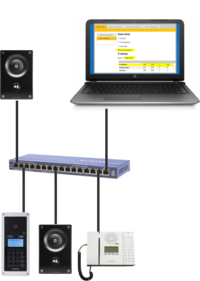
- After the Pulse Server has been configured, connect the rest of the IP intercom stations to the network.
- Wait for the stations to boot up (approximately 60 seconds) before proceeding to the next step.
- Log on to the Pulse Server station using its new IP address.
- Select Server Management > Server Configuration > Directory Settings. You should now see a list of all stations on the network.
- To identify the individual stations, click Play. You will now hear a tone in the loudspeaker of the station you selected.
- Enter Directory number, Name and IP address for all the stations. You can choose to use a static IP address or to obtain IP address from a DHCP server.
- Click Save to push the new settings to all stations, and Apply to do a required system reboot.
Verify System Setup
- To verify that the system is up and running, log on to the Pulse Server station and select Server Management > Server Monitoring
- All stations that have been configured should be displayed in the table. Stations that are up and running will have the status Registered.
- You should now be able call between the stations, and have two-way audio communication
Adding more than 16 stations
The Pulse system supports up to 16 intercom stations without the need of any license. As from Turbine firmware ver. 4.7, the number of intercoms can be expanded to 64 by adding an Intercom extension license (item number 100 9661 001) for each station above 16. See here how to install the license.
Adding a new station to an existing Pulse System
See IP Station Configuration - Pulse mode
Additional configuration
Call Buttons (DAK)
The call buttons (also called Direct Access Key - DAK) can be configured via the Pulse Server or directly on the calling station.
- Via Pulse Server: Log on to the Pulse Server, and select Server Management > Server Configuration > Direct Access Key Settings
- Directly on the calling station: Select SIP Configuration > Direct Access Key Settings.
Related articles:
- Direct Access Key & Ringlist Settings: For details about DAK key configuration
- OLED Labels: How to configure the OLED display used for labeling the call buttons in the station models TCIS-4 and TCIS-5
- Address Book: How to configure and maintain the Address Book used in the station models TCIS-6 and TCIV-6
Call and Audio Settings
From the Pulse Server you get access to a subset of Call and Audio Settings:
- On the Pulse Server, select Server Management > Server Configuration > Call and Audio Settings
The Call and Audio Settings menu include the following parameters:
- Autoanswer: When un-checked the call will be ringing (Private mode). When checked the call will connect straight through (Open mode). An optional field let you specify a delay (in seconds) before the call is auto-answered.
- Relay Configuration: Click on this link to configure the relay operation of the station
- Speaker Volume: This parameter sets the speaker volume for the station.
- Noise Reduction: This parameter enables active noise cancellation. This feature is for stations that are located in noisy environments. A level of 3 or 4 is normally suitable.
By logging on to the station directly, you will get access to more settings:
Relay Settings
All IP Intercom stations (execpt the desktop models) have a built-in relay which can be used for door opening, call indication lamp etc. The relay can be controlled by a DTMF digit, or by a number of different call events and station statuses.
You can access the Relay Configuration page either:
- Via the Pulse Server by selecting Server Mangement > Server Configuration > Call and Audio Settings, or
- By logging on to the station directly, and select SIP Configuration > Relay Settings
For details about relay configuration, see Relay Settings
Inputs and Outputs
The Turbine stations have 6 I/O's which can be used as Inputs or Outputs. By default all I/O's are set as Inputs.
For details about configuration of inputs and outputs, see I/O Settings.
Station Profiles
The Station Profile defines a set of service features and parameters that are available for a group of stations. The following service features and parameters are included in the station profile:
- Outgoing call restriction
- Door opening including remote I/O
- Group Call initiation
- Busy Override
To modify Station Profiles, see Station Profiles
Group Call
The Pulse system supports 4 group calls. A group call is activated by dialing the appropriate code (default 84-87). A ding-dong signal is heard in all member stations. Press the M-key to speak, and C-key to disconnect. From substations without a M-key, the group call is in handsfree mode.
To configure the Group Call feature, see Group Call
Ring List
The Ring List is used to configure Call Escalation (i.e. forwarding of unattended calls), and for Parallel Ringing.
To configure the Ring List feature, see Ring List Function
Virtual I/O [Turbine only]
Virtual I/O is a feature for activating scripts on station events. The supported script languages are Lua and other shell scripting languages. This can be used for example to execute scripts towards other systems, e.g. access control systems, triggered by a DTMF digit. These scripts can be uploaded and configured via the menu options:
- Script Upload
- Script Configuration
- Script Events
The Virtual I/O feature is supported on Turbine stations only.
For more details, see Virtual I/O
Audio Messaging [Turbine only]
Prerecorded audio files can be uploaded to a Turbine IP Station, and the audio messages can be triggered by various events occuring on the station. The audio message files are uploaded from the station webinterface or from the VS-IMT tool.
See Audio Messaging for more details.
Button and LED configuration for customized stations [Turbine only]
When making customized stations based on the Turbine Frontboard, it is possible from the station web interface to define DAK actions and LED behavior. This is supported when front board type is set to TCIS 1/2/3 and TCIV 1/2/3, and the station operates in Pulse or SIP mode.
For more details, see Button and LED configuration for customized stations (Pulse/SIP)
Backup and Restore
From the web interface of the station it is possible to backup and restore the configuration data. See Backup and Restore for more information.
Language Settings
In the INCA type stations it is possible to change the language of the display texts. This does not affect the texts in the web server interface. See Language Settings for details.
Password
The password for web access and for accessing the display setup menus can be changed, see Password (IP Stations).
3rd-party SIP phones
Up to 10 third party SIP phones can be registered to a Pulse system. Each phone requires that a SIP User account is defined on the Pulse Server.
Before adding SIP accounts to the system, you need to install a license for the Pulse 3rd Party SIP phones. When a valid SIP phone license has been installed, the Third Party SIP Terminals parameter will be available.
- Log on to the Pulse Server.
- Select Server Management > Server Configuration > Directory Settings.
- Under Third Party SIP Terminals enter the Directory Number, Name, and Profile for the SIP telephone.
- Click Add followed by Save
The Password field can be left blank. When a password is entered, the SIP phone must register using this password.
Configure the SIP phone
You now have to log into the 3rd-party SIP telephone to configure the SIP account to register it with the Pulse Server station. The Directory Number and Password (SIP Account) created in the section above is used to register the 3rd-party station with the Pulse Server.
Telephone gateway
Before adding a Telephone Gateway to the system, you need to install a license for the gateway. When a valid Gateway license has been installed, the Gateways parameter will be available.
- Log on to the Pulse Server.
- Select Server Management > Server Configuration > Directory Settings
- Under Gateways set the following values:
- - Directory Number: 0
- - Name: <name of your choice>
- - Profile: Default
- Click Add followed by Save
Note: Directory Number 0 is optional as you can use any number to make external calls through the Gateway
Configure the Telephone Gateway
Log into the Telephone Gateway to register it to the Pulse Server by using the SIP Gateway Account created in previous section.
Recommended gateways:
- AudioCodes MP114/118 - Gateway for analog telephone lines
- GSM Gateway - Gateway for the GSM network
VS-Client
Up to 10 VS-Clients (Softclient for Pulse) can be registered to a Pulse system.
Before adding VS-Clients to the system, you need to install a license. Each VS-Client requires a VS-Client license (item number 100 9661 101). When a valid VS-Client license has been installed, the VS-Client parameter will be available.
- Log on to the Pulse Server.
- Select Server Management > Server Configuration > Directory Settings
- Under VS Client enter the Directory Number, Name, and Profile for the client.
- Click Add followed by Save
Pulse Trunking
Pulse Trunking makes it possible to call between different Pulse systems.
The Pulse Server must be a station in the Turbine family with software version 4.2.3.9 or higher. Note that Pulse Trunking is not supported when an INCA Station is used as Pulse Server.
Before adding Pulse Trunking to the system, you need to install a license. When a valid Pulse Trunking license has been installed, the Pulse Trunk parameter will be available.
- Log on to the Pulse Server.
- Select Server Management > Server Configuration > Directory Settings
- Under Pulse Trunk enter:
- - Directory Start: Directory number of first station on other Pulse system site
- - Directory End: Directory number of last station on other Pulse system site
- - (Directory numbers must be globally unique for all stations in a multi-site Pulse system.)
- - Name: Name of other Pulse system site
- - Profile: Type of station
- - Host: IP address of Pulser Server on other Pulse system site
- Click Add followed by Save
Advanced Network Settings
Time Settings
The user is able to configure time by either enabling NTP and specifying NTP server, or setting up time manually. On Master stations with display the configured time is shown on display.
See Time Settings for details.
Firewall
All IP Stations have an embedded firewall. See Firewall for details.
SNMP
A set of SNMP functions are available in the IP station. SNMP (Simple Network Management Protocol) is a protocol for centralizing the management of devices in IP networks.
See SNMP Settings for futher information.
Network Access Control IEEE 802.1X
IEEE 802.1X is an IEEE Standard for port-based Network Access Control (PNAC). It provides an authentication mechanism to devices wishing to attach to a LAN, either establishing a point-to-point connection or preventing it if authentication fails. For details on configuration, see IEEE 802.1X.
VLAN Tagging [INCA only]
VLAN Tagging is the practice of inserting a VLAN ID into a packet header in order to identify which VLAN (Virtual Local Area Network) the packet belongs to. More specifically, switches use the VLAN ID to determine which port(s), or interface(s), to send a broadcast packet to.
For details on configuration, see VLAN Tagging (IEEE 802.1Q).


