Station Web Interface - ICX-AlphaCom mode
From Zenitel Wiki
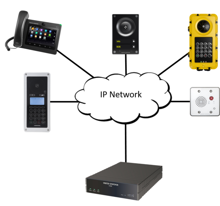
This article describes the various settings availbale through the web interface for Zenitel IP Stations to operate with an ICX-AlphaCom or AlphaCom XE server.
The station web interface
Station Web images and description in this article is based on the latest released software version.

|
The menus and parameters displayed may vary depending on the station type (e.g. Compact, Industrial or Ex). |
Main tab
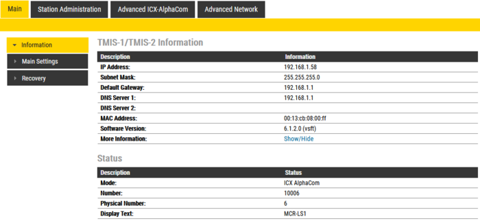
Information
- Log In to the station
- The Information page will now be displayed, showing the IP station configuration and status.
Main Settings
- Click Main > Main Settings to access the page for configuring station mode and IP parameters.
Station Mode: Select the Use ICX-Alphacom radio-button.
Product Model And Accessory: Depending on the type of station hardware, there are different Product models and accessories to choose from. Find your model here: Station Models
Registration Settings:
- ICX-AlphaCom IP-address: Enter the IP address of the ICX-AlphaCom server to which the IP station is to be registered
- Number: Enter the directory number of the station. This must match the directory number defined in the ICX-AlphaCom server
- - If a directory number is not entered, the station will register with its MAC address. The MAC address is found on the Station Information page and needs to be entered in the ICX-AlphaCom server using the AlphaPro PC tool
IP Settings:
- DHCP – Select this option if the IP station shall receive IP Settings from a DHCP server.
- Static IP – Select this option if the IP station shall use a static IP address. Enter values for:
- - IP-address
- - Subnet-mask
- - Gateway
- - DNS Server 1 (option for network administration, not used in ICX-AlphaCom mode)
- - DNS Server 2 (option for network administration, not used in ICX-AlphaCom mode)
- - Hostname (option for network administration)
- Read IP Address: Check the Read IP Address box to enable an unregistered station to speak the IP address when the call button is pressed. "Read IP Address" is default enabled.
- Disable Reset to Factory default settings using frontboard and I/O (not available on all models): Check this option to avoid unwanted or accidental initiation of the factory reset procedure from an input or button.
- Enable RSTP (not available on all models): Check the Enable RSTP box to enable RSTP. RSTP is only required when using redundant networking
- Ethernet Speed 10 Mbits/s (not available on all models): Default Ethernet speed is 100 Mbit/s unless switch is configured to 10 Mbit/s
Click Save followed by Apply to apply the new configuration settings.
Recovery
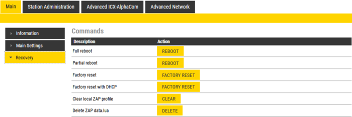
- Click Main > Recovery to access the page for recovery functions.
- Reboot system: Perform a full Linux reboot. No configuration is lost
- Reboot main application: Perform a restart of the intercom application. No configuration is lost
- Factory reset: Set all parameters to Factory Default values. The station will get static IP Address 169.254.1.100.
- Factory reset with DHCP: Set all parameters to Factory Default values. The station will get IP Address from DHCP server. If no DHCP server in the network, it will get a random 169.254.x.x IP address.
- Clear local ZAP profile: For special purpose
- Delete ZAP data.lua: For special purpose
Station Administration tab
Change Password
The password for web access and for accessing the display setup menus can be changed, see Password (IP Stations).
Manual Upgrade
The software of the station can be upgraded via the web interface. see Turbine_Software_Upgrade for details.
Backup and Restore
From the web interface of the station it is possible to backup and restore the configuration data. See Backup and Restore for more information.
Logging
From the web interface of the station it is possible to activate logging, which can be useful for debugging and troubleshooting purposes. See Logging - IP Stations for more information.
Advanced ICX-AlphaCom tab
Audio
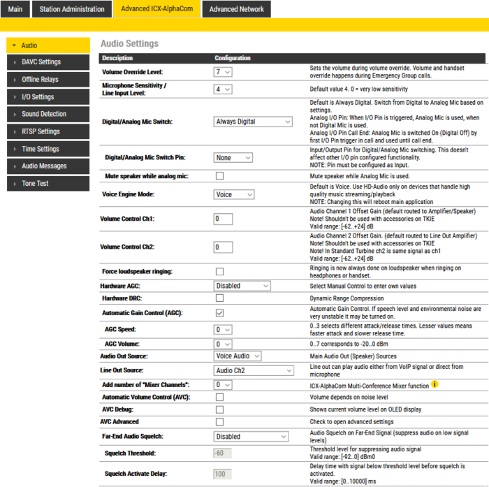
To configure audio settings select Advanced ICX-Alphacom > Audio from the menu

|
The menus and parameters displayed may vary depending on the station type (e.g. Compact, Industrial or Ex). |
| Item | Description | Range | Default |
| Volume Override Level | This setting determines the volume to be used in the station when receving audio and the Volume Override feature is activated, see Volume Override for more details. | 0-8 | 7 |
| Microphone Sensitivity/Line Input Level | If used as a local PA panel, a setting in the 1 to 3 range will reduce the chance of acoustic feedback (howling) | 0-7 | 4 |
| Digital/Analog Mic Switch | Switch from Digital to Analog Microphone based on settings | ||
| Always Digital | The digital mic is always active | Yes | |
| Always Analog | The analog mic is always active | No | |
| Analog I/O Pin | When I/O Pin is triggered, Analog Mic is used, when not Digital Mic is used | No | |
| Analog I/O Pin Call End | Analog Mic is switched On (Digital Off) by first I/O Pin trigger in call and used until call end. | No | |
| Digital/Analog Mic Switch Pin | Input/Output Pin for Digital/Analog Mic switching. This doesn't affect other I/O pin configured functionality. NOTE: Pin must be configured as Input. | I/O 1-6 | None |
| Mute speaker while analog mic | Mute speaker while Analog Mic is used. | Disabled | |
| Voice Engine Mode | Use "HD-Audio" only on devices that handle high quality music streaming/playback, typically IP loudspeakers and Turbine kits used as PA interface. | ||
| Voice | Regular audio quality | Yes | |
| HD-Audio | Play audio in PCM L16/48kHz format | No | |
| Volume Control Ch1 [Turbine Compact only] | Audio Channel 1 Offset Gain (default routed to Amplifier/Speaker) | -62..+24 dB | 0 |
| Volume Control Ch2 [in standard Turbine ch2 is same signal as ch1] | Audio Channel 2 Offset Gain. (default routed to Line Out Amplifier) | -62..+24 dB | 0 |
| PTT with internal route | Enable this option to use DAK1 as M-key | Disabled | |
| Force loudspeaker ringing | Enabling this option will route the ringing sound out on the speaker, even if handset or headset is used | Disabled | |
| Hardware AGC | |||
| Disabled | Hardware AGC not in use | Yes | |
| Quiet Area | Enables hardware AGC with parameters adjusted for use in quiet areas | No | |
| Noisy Area | Enables hardware AGC with parameters adjusted for use in noisy areas | No | |
| Manual Control | Enables hardware AGC where parameters can be customized | No | |
| Hardware DRC | Enables Dynamic Range Compression | Disabled | |
| Automatic Gain Control (AGC) | If speech level and environmental noise are very unstable it may be turned on | Disabled | |
| AGC Speed | selects different attack/release times. Lesser values means faster attack and slower release time | 0-3 | 0 |
| AGC Volume | Range corresponds to -20 - 0 dBm | 0-7 | 0 |
| Audio Out Source | Select which audio source to send to the loudspeaker output | ||
| Voice Audio | Play audio from VoIP signal | Yes | |
| LineIn Idle | Play audio from the Line In input when the station is in idle. During a call, play audio from the VoIP signal | No | |
| LineIn Idle+GPIO-6 | If input 6 is activated while the station is in idle, play audio from the Line In input. Else play audio from the VoIP signal | No | |
| Audio Input Source | Select which audio source to use as input source | ||
| Normal Microphone | Select this option when using an electetret microphone as audio source | Yes | |
| Line In | Select this option when using an external audio source with line level | No | |
| Line Out Source | Line out can play audio either from the VoIP signal or directly from the microphone input | ||
| Audio Ch2 | Play audio from the VoIP signal | Yes | |
| Microphone before AEC | The analog and digital microphone signal is sent to Line Out. The speaker signal is picked up by the microphone through the air, and also sent to the Line Out. There is no signal processing | No | |
| Microphone after AEC | Station is in Open Mode: The microphone signal is sent to Line Out. The speaker signal is picked up by the microphone through the air, and also sent to the Line Out. Echo canceling is not working, but Noise reduction works. Audio from mic should be heard all the time on Line Out, audio from other party should be heard only when PTT is pressed by other party. Station is in Full Duplex Mode: The microphone signal is sent to Line Out. |
No | |
| Add number of "Mixer Channels | Select the number of mixer channels when the station is used for audio mixing in the ICX-Alphacom MultiConference feature. Each mixer channel will register to the ICX-AlphaCom server with its own directory number | 0-6 | 0 |
| Automatic Volume Control (AVC) | Check this box to automatically adjust the volume according to the background noise level | Enabled | |
| AVC Debug | Check the box to show adjusted total gain with offset adjust in parentheses on OLED display (for TCIS-4/TCIS-5/TCIS-6). Total gain is referenced to 0 dB as “standard maximum gain” (level 7), and volume override levels (level not supporting open-duplex voice) as positive gain values. | Disabled | |
| AVC Advanced | Check to open for more advanced AVC settings | Disabled | |
| AVC Lower Threshold | Threshold level for AVC start working | -92 - 0dBm | -45 |
| AVC Upper Threshold | Threshold level for AVC stop working | -92 - 0dBm | 0 |
| AVC Attack Rate | How fast gain is raised when ambient noise level is increasing | 0 - 100 (0.1 - 10 dB/sec) | 2 |
| AVC Decay Rate | How fast gain is reduced when ambient noise level is falling | 0 - 100 (0.1 - 10 dB/sec) | 10 |
| AVC Hysteresis | Required mic-signal change level before new gain adjusted. This is applied when change in gain directions | 1 - 10dB | 3 |
| AVC Lockout Time | Time for successive frames after AVC lock, due to far-end avtive or optional high near-end signal, before commencing AVC adjustments. A negative sign locks AVC if signal above upper threshold | 1 - 10dB | 1 |
| Far-End Audio Squelch | Enable Audio Squelch on Far-End Signal (suppress audio on low signal levels) | Disabled | |
| Squelch threshold | Signal level below this theshold will be suppressed to silence | -92 - 0dBm | -60 |
| Squelch Activate Delay | Delay time with signal below threshold level before squelch is activated. Squelch is turned off again on first audio frame with level above threshold. This will implement a simple hysteresis hindering too rapid on/off with a signal changing around threshold | 0 - 10,000ms | 100 |
DAVC Settings
The Distributed Automatic Volume Control (DAVC) is an algorithm which is using one or more microphones ("AVC Source") to measure the ambient audio/noise level, and adjusts the loudspeaker output level of the PA amplifier ("AVC Receiver") according to the ambient audio level.
See the article Distributed Automatic Volume Control (DAVC) for details about this feature.
Offline Relays
Fallback mechanism that makes it possible to designate one input/dak per relay which will activate the relay on press, and deactivate on release when the ICX-AlphaCom is offline
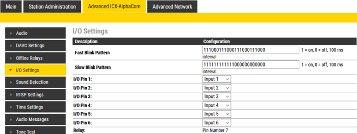
I/O Settings
These settings let you choose if an I/O should be used as an Input or as an Output. By default all I/O's are set as Inputs.
- Select Advanced ICX-AlphaCom > I/O Settings from the menu
- Select either Input or Output options from the drop-down box for I/O Pins 1 to 6.
See also the article Turbine Inputs and Outputs in ICX-AlphaCom.
Sound Detection
The Sound Detection, also known as Voice Activity Detection (VAD) samples the audio level from the microphone located in the IP Station. If the audio level meets defined criterias an action in ICX-AlphaCom can be triggered.
Read more about Sound Detection.
RTSP Settings
- Enable RTSP - enables RTSP traffic by allowing/blocking traffic from/to RTSP port
- RTSP Port - defines RTSP port - by default RTSP port is set to 554
- Enable RTSP Authentication - enables mandatory usage of RTSP credentials on stream setup
- RTSP URL - RTSP URL that can be copied into RTSP player. All supported RTSP streams are listed here: audio-only, video-only and audio+video stream URL for video Turbine devices and audio-only stream URL for other Turbine devices.
- Audio Source - defines when acoustic echo canceler is applied to mic+speaker voice. With this setting it is possible to choose whether only microphone signal is sent to RTSP stream or both microphone and speaker signals are sent to RTSP stream. On video Turbine stations this option can be defined separately for each stream.
Video Settings
Advanced Video Settings
TCIV+ and TCIV Video Stations also have settings for ONVIF. For details, see Advanced video settings for TCIV+ or RTSP and ONVIF Settings for TCIV Stations.
OLED Labels
See article OLED Labels on how to configure the display in the station models TCIS-4 and TCIS-5.
Address Book
See the article Address Book on how to configure the address book of the station models TCIS-6 and TCIV-6/TCIV-6+.
Keyboard Settings
Applies to the station models TFIE-x (Industrial station) and TFIX-x (Explosion proof station). See article TFIE Keyboard Settings for more details.
Time Settings
- Select Advanced ICX-AlphaCom > Time Settings from the menu
Time Settings: You can enable Network Time Protocol, select the time zone and set the hostname or the IP address of the NTP server.
Audio Messages
A Turbine station can play a custom media (WAV) file when connection to the ICX-AlphaCom server is lost. The station can also play a custom media file when pressing the call button (or activating an input) and the call setup fails because the station is offline. See Audio Messages - Turbine for more detasils.
Tone Test
- Select Advanced ICX-AlphaCom > Tone Test from the menu
Read more about tone test in ICX-AlphaCom here: Line_monitoring#Tone_test
Advanced Network tab
SNMP
A set of SNMP functions are available in the IP station. SNMP (Simple Network Management Protocol) is a protocol for centralizing the management of devices in IP networks.
See SNMP in IP Stations for futher information.
802.1X
IEEE 802.1X is an IEEE Standard for port-based Network Access Control (PNAC). It provides an authentication mechanism to devices wishing to attach to a LAN, either establishing a point-to-point connection or preventing it if authentication fails. For details on configuration, see IEEE 802.1X.
VLAN
VLAN is not applicable for the Turbine series. Only for IP Desk Master -V2, IP Flush Master -V2 and the INCA family. See article VLAN Tagging (IEEE 802.1Q) for details.
Firewall
All IP Stations have an embedded firewall. See Firewall for details.


