Users & Stations (AlphaPro)
From Zenitel Wiki
From the Users & Stations window you can inspect and modify the properties of intercom stations.
Common information
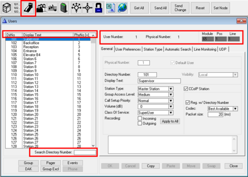
The Users & Stations window contains some information which is available regardless of which tab has been selected:
- User Number: Range 1 - 600. The Directory Number of a station is linked to the User Number, which is linked to the Physical Number. By default there is a 1 to 1 link between User Number and Physical Number.

|
It is possible to define several Users on the same Physical Number. This makes it possible for one station to have several Directory Numbers. This type of configuration is by default disabled, but can be enabled be selecting from the main menu bar View > Users&Stations: Allow editing of physical numbers. |
- Physical Number: Range 1 - 552. Each intercom station has a physical number. For analog intercom stations the physical number is determined by the position of the line board (ASLT or ATLB-12), and in case of MultiModule system it is also determined by which module the line board is located. For IP intecom stations the physical number is a virtual number. The physical number is linked to the "User Number", which is linked to the Directory number.
- Module, Pos, Line: Shows where an analog station is physically connected. The numbers are automatically calculated from the physical number. Module shows which of the 4 modules (65-68) in a MultiModule system, Pos shows the line card position (1-23), and Line shows which of the 6 line circuits on the ASLT line card the station is connected to.
- Search Directory Number: Type in a directory number you are seaching for. The listbox will be sorted as you type in the number.
- Sorting the listbox: Click on one of the headers in the listbox DirNo, Display Text or PhyNo to sort the list according tho the selected choice. By default the list is sorted on increasing physical numbers.
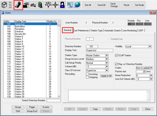
General tab
- Physical Number: Range 1 - 552. Each intercom station has a physical number. For analog intercom stations the physical number is determined by the position of the line board (ASLT or ATLB-12), and in case of MultiModule system it is also determined by which module the line board is located. For IP intecom stations the physical number is a virtual number. The physical number is linked to the "User Number", which is linked to the Directory number.

|
In hybrid exchanges (AlphaCom XE7, XE20 and XE26), where there is a mix of analog and IP stations, you should avoid using physical numbers for IP Stations that later might be used for analog intercom stations. |
- Default User: It is possible to define several Users on the same Physical Number. This makes it possible for one station to be called by several Directory Numbers. One of the Users must be set as the "Default User". The station will use Caller ID, DAK keys, Group Call membership etc. from the "Default User". Configuration of multiple users on one station is by default disabled, but can be enabled be selecting from the main menu bar View > Users&Stations: Allow editing of physical numbers. Now you can select a free User from the User list box (normally user 553 - 600), and assign it the same physical number as the real station. Only the "Default User" will be available in the AlphaCom OPC Server.
- Directory Number: The number to dial to call to the station. The directory number can be any 1 to 8 digit number.
- Visibility: Is used in AlphaNet systems for easy maintenence of station numbers using Cluster Programming. By setting the Visibility to "Cluster Global", the station will automatically be created as a Global Number in the other AlphaCom Cluster nodes. See Cluster Programming for details.
- Display Text: This text will show in the stations display in idle, and is used as Caller ID when a call is set up. Maximum 16 characters. Depending on station type, and the number of digits in the directory number, the whole text might not be visible in the display of the station.
- Station Type: Select the type of station/device that is connected to the actual physical number. The following options are available:
- Master Station (default): Can be used for all stations. Recommended for master stations with full keypad, with or without display.
- Substation: Blocks the station from receiving Call Back message (which will generate annoying blink and bleep in the station). Recommended station type for:
- PNCI: Was originally designed for the now obsolete PNCI telephone interface. Can also be used for regular intercom stations. During conversation with an intercom station set as "PNCI", digits will not be handled by the AlphaCom server, but will be reported to the Event Handler, event 25, and can be used for remote control operations during a call.
- CRM: (Control Room Master). This option is applicable for any (analog or IP) station with display used for Call Queueing (Call Request handling). This setting will modify the display layout. IP Stations set as "CRM type" will have the display backlight permanently on.
- Display station: For IP Stations this option will utilize smaller fonts in the display. For analog stations it will provide faster detection of line errors.
- DualDisplay: Use this option for DualDisplay stations (1007007000/1008007000). This setting will enable the DAK display used for labelling of the DAK keys.
- Custom 2: Not in use
- CCoIP Station: Enable this flag when an IP Station is assigned to this physical number.
- Reg. w/Directory Number (default): When enabled, the IP Station will register to the AlphaCom server by its directory number. When disabled, the IP Station can register to the AlphaCom server by its MAC address. The MAC adress of the IP Station must be filled in.
- Codec: Set which codec to use. Normally use the default "Best Available"
- Packet size: Default is 20 ms audio packet size
- Noise Reduction: Enable the Active Noise Cancellation function of the station. This will reduce background noise from the surroundings. 0 = Noise Reduction is Disabled
- Line Out Volume (dB): Sets the volume on the Line Out output on Turbine devices. Not applicable to INCA devices.
- SIP Station: Enable this flag when a SIP phone is assigned to the physical number.
- Codec: Set which codec to use. Default is "G711 u-law"
- Packet size: Default is 20 ms audio packet size
- Related to Trunk: Enter the node number (1-254) of the SIP Trunk Node. This option can be used if a SIP phone is registered to a remote SIP Server, and there is a SIP trunking connection to that SIP server. When the SIP Station number is dialed, the AlphaCom will send an INVITE message out on the SIP Trunk, containing the dialed SIP Station number. See SIP Devices - creating an account and SIP Trunk Station
- 200 OK replies during busy/queue: When enabled the SIP station will receive 200 OK instead of 180 RINGING/182 QUEUED when calling a private/busy station. This means that the audio connection will be established with the AlphaCom/ICX also when calling a station in private mode or a busy station, and the ringing tone or busy tone from the AlphaCom/ICX will be heard. This also makes it possible to use override features, such as Private Ringing Override or Busy Override.
- Group Access Level: Is used to restrict the access for a station to activate group calls. Each group can be assigned on out of three possible access levels: Low - medium (default) - high. To be able to access a group call, the station must have the same or higher level than defined for the group
- Call Setup Priority: This setting specifies how outgoing calls from this station are handled; see also Call Setup Priority.
- Low: Calls will always be in private ringing mode, regardless of the private/open settings of the called station
- Normal (default): Calls will connect in private or open mode depending on the private/open settings of the called station
- High: Calls will always be in open mode, regardless of the private/open settings of the called station. Will also override any absence settings on the station.
- Alarm: Calls will always connect in open mode, also if the called station is busy in another conversation or if there are no more speech channels available.
- Volume (dB): Sets the loudspeaker volume of the station. 0 dB is default level.
- For IP Stations there are 8 steps available. The change will take effect after a Send operation.
- For analog stations the volume setting will change the level out from the ASLT line card. Normally used to compensate for volume loss on long lines. Available values are -14 dB to 16 dB. The exchange must be reset for the change to take effect.
- Class of service: The Class of service (CoS) setting determines what features in the system this station has access to. There are 16 different classes available. The content of each Class of Service can be modified in a separate window.
- The following classes have a default setup (which can be changed):
- Class of service 1: Default features for all stations in the system.
- Class of service 15: Default features for all PNCIs connected to the system.
- Class of service 16: Includes all features. Default for the SuperUser, the station connected to physical number 1.
See the Class of Service feature lists on AlphaCom Feature List
- Recording: When enabled, the conversation audio from both parties in the conversation will be sent to external audio recorder if such recording device is connected. See AlphaCom Recording Interface
- Incoming: Recording will take place when receiving a call
- Outgoing: Recording will take place when making a call
- Apply to All: The Recording settings (Incoming and/or Outgoing) on this station will be applied to all stations when "Apply to All" is pressed.
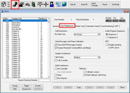
User Preferences tab
- Call Restrictions - No Calls From: Calls from stations which are member of the group selected will be rejected.
- Audio Program Sequence - Sequence 1/2: A station (e.g. in a prison cell) can step through a range of Audio Programs. There are two audio program sequences to choose from. See Program Step feature.
- Help Messages and Status Indication
- Voice (ASVP) Message Wanted: Enable (default) or disable the Voice Message Features for the station. This includes all absence messages, voice mail messages and voice help, as well as the Call Requester message (e.g. "Your call is registered, please wait..").
- Feature Reminder Wanted (Blink and Bleep): Enable (default) or disable feature reminder for the station. The feature reminder is a flashing LED and a bleep every minute to indicate that there are messages present, or that Call Forwarding is active on the station.

|
When "Feature Reminder Wanted" is disabled, also the ringing tone when receiving a Ringing Group call is muted |
- OPC - Disable reporting to OPC Server: When enabled, this station will not be discovered by the OPC Server or by the VS-SDK for AlphaCom, or any applications using the SDK, such as VS-Operator. The station will not consume any OPC/API license when this flag is enabled.
- Simplex Conference
- Talk Priority: There are four priority levels, Low, Medium, High and Alarm. There are two mechanisms taking place:
- To be able to talk into the conference, the Talk Priority of the station (default is "Medium") has to be higher than the Talk Priority of the Simplex Conference (default is "Low"). If not sufficient priority, the station will be able to listen, but rejected when attempting to do talkback.
- A station with a higher talk priority than the current talker will override the current talker.
- Talk Override: If this flag is set, and the station has the same talk priority as the current talker, he will override the current talker. If several stations have this flag enabled, and they have the same Talk Priority, the last station pressing the M-key will be the talker.
- Multi Conference The MultiConference is an AlphaCom feature that makes it possible for operators to listen to multiple Audio Sources in a mix. The operator can talk back to individual sources, or to all sources in one go.
- Mix Controller: This station controls which mix channels to send to the mixer.
- Mixer: This station is used as a mixer for the Mix Channels. Can be the same device as the Mix Controller, or a separate (Turbine) device
- Mix Channel: Virtual station providing audio to the mixer.
- Talkback source: When Mixer and Mix Controller are separated on two different devices, one can choose if the talkback source (i.e. the microphone) should be from one or the other
- Multi-Talkback with M-key: When enabled, the M-key/PTT will do talkback to all active channels
- Use Workchannel: When enabled, the M-key/PTT will do talkback to a preselected "work channel". The operator can change work channel from his panel
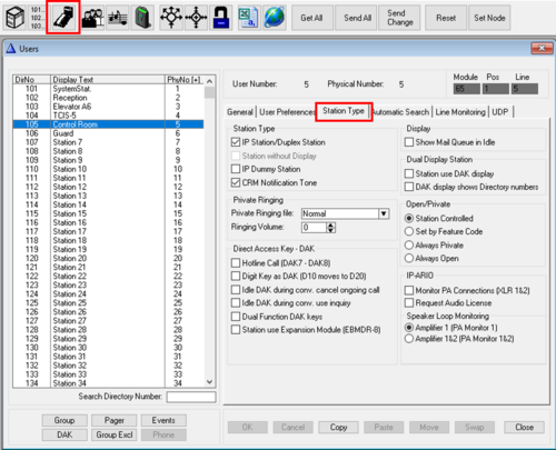
Station Type tab
Station Type
- IP Station/Duplex Station: Disable voice switching and force this station in open duplex. Automatically enabled for CCoIP stations.
- Station without Display: Applicable to analog ASLT stations only. This setting is optional, and will disable the automatic display/non-display detection on the ASLT board, and ensure a faster and more reliable line error reporting for an analog station without display receiver.
- IP Dummy Station: This station is a virtual station, used for special applications. An IP Dummy station consumes an IP Station License.
- CRM Notification Tone: When a station receives a Call Request, this is by default indicated by a Notification Tone (dut-dut-dut-dut). If the Call Request is received during a conversation, the conversation is interrupted for a short period. If this flag is disabled, there will be no notification tone, and no interruption of any ongoing call. This flag is applicable only when Station Type is set to "CRM". Default enabled.
Private Ringing
- Private Ringing file: Use customized ringing tone on incoming calls to this station. Note that outgoing calls from this station will use standard private ringing tone. A wav file with the wanted ringing tone must be uploaded to the ICX-AlphaCom via the web interface. For details, see Private Ringing, Customized ringing tone
- Ringing Volume: Sets the "Private Ringing" volume of an IP station.
- Value 0: Use the station volume.
- Value 1 - 30: Override the station volume, and use this value during ringing. When the call is answered and the ringing stops, the initial volume setting will be restored.
- The value 1 equals minimum level 1 set on the station, and will reduce the ringing volume compared to default volume level.
- The value 13 equals default volume level.
- The value 30 equals maximum level (Level 8 set on a display station).

|
|
Direct Access Key - DAK
- Hotline Call (DAK7 - DAK8): When this flag is enabled, lifting the handset will dial the number on DAK 7, and replacing the handset willl dial the number on DAK 8. See Hotline Call for more details.
- Digit Key is DAK (D10 moves to D20): When this flag is enabled, the digit keys 0-9 will work as Direct Access Key (DAK) 1-10. Regular dialing will no longer be possible. If the station has DAK keys (incl. hotline), they are moved to DAK 11 - 20.
- Idle DAK during conv. cancel ongoing call: When enabled one can go from DAK key to DAK key without the need of pressing the C-key in between. When a new DAK key is pressed, the current converation is cancelled, and the new one established. From AMC v. 13: Pressing the same DAK key twice will cancel the conversation (toggle conversation on/off).
- Idle DAK during conv. use inquiry: Pressing a DAK key during a call will put the current call on hold, and connect to the directory number configured on the DAK key pressed. (Same as dialing "2" + directory number)
- Dual Programming DAK keys: Enables the possibility of dialing from idle and execute a feature during the call. Example: DAK string "D 6 I 104" will call station 104 when the DAK key is pressed from idle, and will activate Door Opening feature ("6") when pressed during the conversation.
- Station use Expansion Module (EBMDR-8): Check this flag if the station is an ECPIR station with Expansion Module EBMDR-8, and you also want to use the inputs on the ECPIR panel. See Turbine Inputs and Outputs in ICX-AlphaCom for more details.
Display
- Show Mail in Idle: This setting is mainly used by analog stations with 2-line display used for Call Queuing, e.g. model 1007072090. When enabled the display will show the call queue directly, it is not neccessary to enter into the call queue by dialing code 70 first.
Dual Display Station
- Station use DAK display: If a Dual Display Station is used for Call Queing (i.e. Station Type = "CRM"), this flag must be set to enable the second display used to label the DAK keys.
- DAK display shows Directory numbers: The DAK display of the Dual Display Station will show the Directory Number in the programmed button instead of the user name (text)
Open/Private
- Station controlled: The private/open mode is controlled by the user, by either pressing C-key for 2 seconds (IP Station), or by using the Private/Open slide switch (analog station)
- Set by Feature Code: Private/open mode is controlled by feature codes 7887 (Private) and 7886 (Open)
- Always Private: This will force the station in Private mode, regardless of the Private/Open setting on the station.

|
The Always Private flag is also available from the web interface of the AlphaCom, in System Configuration > Stations. The setting in AlphaWeb will be overwritten by a SendAll from AlphaPro |
- Always Open: This will force the station in Open mode, regardless of the private setting on the station.
IP-ARIO
- Monitor PA Connections (XLR 1&2): Enables supervision of the XLR outputs of the IP-ARIO. An error in the cable between the IP-ARIO and the amplifier is reported as event type 13, subevent 14 and 22 (XLR 1), and subevent 18 and 23 (XLR 2). See PA_Failure_State_System for more details.
- Request Audio License: If the IP-ARIO is used for audio distribution, e.g. PA interface or mobile radio integration, this flag must be set. An IP-ARIO license is required when using IP-ARIO for audio distribution. If only outputs and/or inputs are used on the IP-ARIO, and no audio features, then this flag should be unchecked, and no IP-ARIO license is required.
Speaker Loop Monitoring: If the PA amplifier provides a pilot-tone, the 100V speaker line can be wired back to the "PA Monitor" input of the IP-ARIO for monitoring of the speaker line.
- Amplifier 1 (PA Monitor 1): Enables monitoring and error reporting of the speaker line of the first amplifier connected to the IP-ARIO. Errors are reported as event type 13. See PA_Failure_State_System for more details.
- Amplifier 1&2 (PA Monitor 1&2): Enables monitoring and error reporting of both speaker lines when connecting two amplifiers to the IP-ARIO. Errors are reported as event type 13. See PA_Failure_State_System for more details.
Automatic Search tab
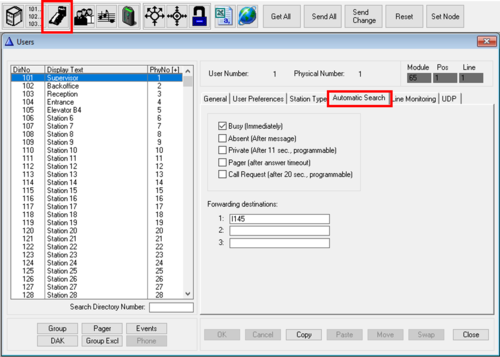
A call can automatically be forwarded when the called station is in a certain state.
Forwarding conditions:
- Busy (Immediately): If the called station is busy, the call will be forwarded to the first directory number in the "Forwarding Destinations" list. If this station is also busy, it will try the next in the list, and if also busy, it will set up the call to the last in the list.
- Absent (After message): If the called station is in absence state, the call will be forwarded to the first directory number in the "Forwarding Destinations" list. The call is forwarded after the absence message has been played. If this station also is in Absence State, it will go to the next in the list.
- Private (after 11 sec., programmable): If the call is in private ringing mode, and the call is not answered within the preset time, or if the user rejects the call by pressing the C-key during ringing, the call will be forwarded to the first number in the "Forwarding Destinations" list. If this station is also in private mode, the call will be forwarded to the next in the list if not answer within due time, and finally to the last station in the list. The timer is by default 11 sec, but can be modified, see Auto Search Time.
- Pager (after answer timeout): The call will be forwarded if there is no answer to a wireless pocket paging call. The call is forwarded when the time-out for pager answering has expired
- Call Request (after 20 sec., programmable): An unattended Call Request or Ringing Group call will be forwarded to the first directory number in the "Forwarding Destinations" list after a preset time. The time is by default 20 sec., and can be modified, see Call Request search string Timeout. Note that when using Call Request forwarding, any further forwarding must be configured in the Automatic Search settings of the target station.
Several conditions can be enabled at the same time.
Forwarding Destinations:
- Both stations and features be used as destination
- If the forwarding destination is Call Request (e.g. "I 627 I 123"), any further forwarding must be configured in the Automatic Search settings of the target station (e.g. 123)
- If the forwarding destination is a Ringing Group (e.g. "I 6701"), any further forwarding must be configured in the Automatic Search settings of one of the stations in the Ringing Group
Examples:
Manual Search:
- When pressing digit "9" during a call (or during ringing), the call will be transfered to the first in the "Forwarding destinations" list
- Press "9" again to get transfered to the next in the list
Line Monitoring tab
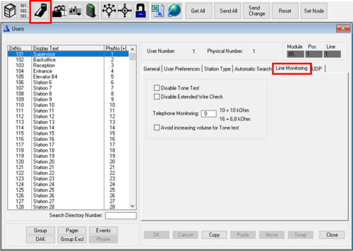
- Disable tone test: When Tone test is enabled, it is possible to disable the test per station by setting this flag. This option is used for stations with low crosstalk between speaker and microphone, as the tone test relies on the fact that the microphone can pick up the sound emitted from its own station speaker. The tone test should be disabled for:
- IP Speakers
- PA and Mobile Radio interfaces
- Stations with dynamic microphone
- Industrial stations with noice cancelling microphones
- Locations where the tone test is considered to be annoying to the user
- Disable Extended Wire Check: Extended Wire Check is activated on the system level, causing LED blinking every 2-5 minutes. This feature should be disabled for guard stations etc., as LED blinking also is used to indicate incoming call requests. The 'Disable extended wire check' flag can be used for this purpose.

|
"Extended Wire Check" is applicable for analog stations connected to ASLT boards only |
- Telephone Monitoring: Enter a threshold value for checking DTMF telephone connected to ATLB card. The telephones must be fitted with a parallel resistor close to the telephone. Line monitoring (wire break) is activated per phone by entering:
- Value 10 = resistor 10 kOhm
- Value 16 = resistor 6.8 kOhm

|
"Telephone Monitoring" is applicable for analog DTMF phones connected to ATLB boards only |
- Avoid increasing volume for Tone test: If the tone test fails, the default behaviour is that the test will be repeated up to three times, every time with an increased volume. When this flag is enabled, the test will be repeated without increasing the volume.
UDP tab
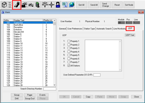
UDP is short for User Defined Property. An UDP group is a group of stations that are used by the Event Handler to construct rules that applies to a group of stations. There are 8 UDP groups available. By default all stations are included in UDP group 8. One station can be member of several UDP Groups.
- User Defined Parameter(%1.EXP): A station can be assigned an User Defined Parameter consisting of up to 4 characters. This parameter can be read from the Event Handler using the macro %1.exp or %2.exp.
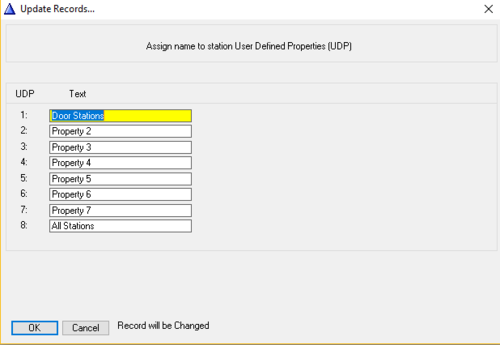
- UDP Text: Each UDP Group can be assigned a text to describe what the UDP Group is used for. This text will also appear in the Event Handler when refering to the UDP Group.
Group
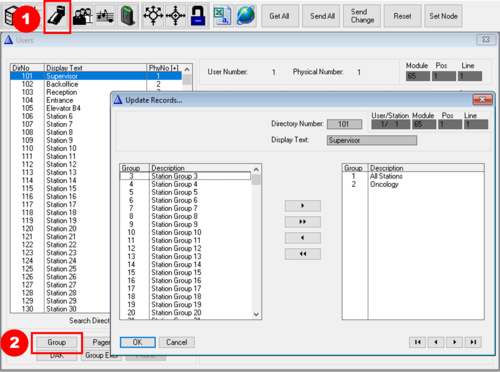
From this window you can define which station group(s) one particular station should be member of.
- On the left side there is a list of all station groups that this station is not member of.
- On the right side there is a list of all station groups that this station is member of.
- Use the arrow buttons, or doubleclick on a station group, to move it from one list to the other.
Pager
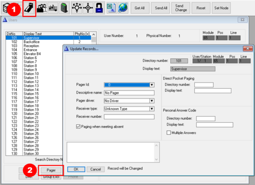
The AlphaCom system can be interfaced to wireless pocket paging system using the ESPA 444 protocol. In this window the pager receivers are defined and linked to intercom stations. The pager receivers can also be defined in the Pocket Pagers window. For more details, see also main article: Pocket Paging.
- Pager Id: The pager identification (1 - 600 ) is used internal by the AlphaCom to separate each pager.
- Descriptive name: The name you enter here is also displayed in the list of pocket pagers. Note that this text is not transferred to the AlphaCom server. It is stored locally on the PC only
- Pager Driver: The following pager driver options are available:
- No driver - default
- Tateco
- Ericsson
- Multitone
- Receiver type: The following receiver types are available:
- Unknown
- Tateco 800/900
- Multitone RPR 550
- Ericsson PSP800
- Multitone RPR 530
- Receiver number: Must correspond to the ID of the pocket pager receiver. Usually the number shown in the pager display when the pager is turned on.
- Paging when meeting absent: When this flag is enabled (default), this station is allowed to activate the pocket pager after having called to a station which is in absence status (e.g. "Busy at the moment"). When the flag is disabled, this station will not be able to activate the pocket pager when the intercom station is in absence status. Hence the user with the pocket pager can control the possibility to be paged simply by turning absence status on or off on his intercom station.
Direct Pocket Paging:
- Directory Number: Directory number to activate Pocket Paging to this pager directly, without calling an intercom station first. Dial: <Direct Pocket Paging dir. no> + <paging type, e.g. 44,45,46,47>.
- Display Text: The display text for the Direct Pocket Paging number
Personal Answer Code:
- Directory Number: The directory number for the personal answer code (if any) for this pager
- Display Text: The display text for the personal answer code (if any) for this pager
- Multiple Answers: When enabled one can send a message to a group of pagers and make it possible for all of them all to answer the paging. The pager group must be set up in the paging system. Applies only to paging using the 47 code.
Events
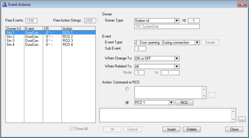
The Event Handler is based on the concept that when intercom functions run, they report 'events' to a part of the software called the Event Handler. The event can be described as a trigger that sets off an action in the system depending on the information entered here in AlphaPro.
Free Events: Shows how many events are free out of the total of 2000 events.
Free Action Strings: Each line of action commands count as one Action String. If the line is longer than 16 characters, it will count as 2 action strings. This filed shows how many action strings are free out of the total of 2000 available action strings.
Show All: When checked, all events in the system will be shown, not only events for the particular station highlighted when the Event window was opened.
Owner. The owner is the source which triggers the event.
- Owner type. The options are:
- Station Id: A single station. The Id = Physical number of the station
- Stations w. UDP: A group of stations. The Id = UDP group 1 - 8
- Scheduler: Scheduler use the Realtime clock of the AlphaCom as event owner. Event can be configured to trigger at specified hours, weekdays or dates
- EDI Text Config: Trigger event when receiving text on an EDI port
Event
- Event Type: Select which event should cause the action. Here an overview of event types.
- Details: This button is enabled when choosing the Event Type: 1 - Audio. One can then choose which type of audio to trigger the event. See Audio_(Event_Type)
- Sub Event: Some events have a subevent which makes it possible to filter on more options than only the main event it self.
- When Change To: The action is executed at a specific event transition, i.e. when the defined event goes on and/or off. The options are:
- OFF - The event is triggered only when the event goes off
- ON - The event is triggered only when the event goes on
- ON or OFF - The event is triggered when the event goes on, and also when the event goes off
- When Related To
- All: The event is carried out with no check on the related number, i.e. works for all stations. Many events have no related number, and in that case the fields are not available
- Directory Number: The action is executed when the event owner is connected to the defined station or feature directory number. The id field has two parts:
- Node: An AlphaNet node number (0 = own server). ID: The Directory number of a station or feature
- Stations w. UDP: The action is executed when the event owner is connected to any station which is member of the specified UDP group. The Id specifies the UDP group 1-8.
Action Command or RCO
- When the upper radio button is selected, you can write action commands which will be executed when the event is triggered. One command per line.
- When the lower radio button is selected, you can select one RCO (Remote Control Output) to be operated by the event.
- The button RCO opens the RCO table, where you can map logical RCO numbers to physical outputs.
DAK
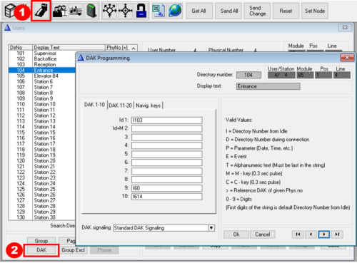
Most intercom stations are equiped with one or more DAK keys (Direct Access Key, also known as speeddial button). The DAK key makes it possible to dial a complete number (or sequence of numbers) by one button press.
DAK 1 - 10: Enter the directory number to be dialed when the corresponding DAK key is pressed.

|
|
DAK 11 - 20: Enter the directory number to be dialed when the corresponding DAK key is pressed.
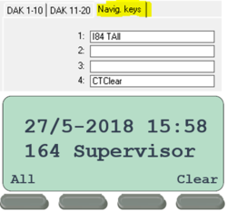
Navig. keys: These are the keys below the display on DualDisplay station and IP Stations with display. The Navigation Keys are reported as DAK 21-24, unless the "Station Type" = CRM. Then the Navig. Keys are reported as DAK 101-104 (to avoid conflict with the DAK 48 panel).

|
When configuring a station to be Station Type: "DualDisplay" or Station Type: "CRM", the Navig buttons are automatically filled in by AlphaPro |
DAK Signaling: These options are applicable to analog stations on ASLT board only. Options available:
- Standard DAK Signaling: This option is used by all types of analog intercom stations, except the PrisCom station
- DAK signaling supported by the PrisCom station:
- Two Tone DAK signaling: The DAK signaling is using a combination of two tones, instead of the standard DAK signaling which is using Current Loop (M) + tone.
- Two Tone DAK signaling w/Ack: When the AlphaCom receives a DAK key signal from a PrisCom station, the AlphaCom will send an acknowledge message by the Display Text Protocol. The station will acknowledge this by sending tone 18. This is the option normally used by the PrisCom station, and Station Kits 1007060105 and 1007060100
- Two Tone DAK signaling w/IND Ack: When the AlphaCom sends the IND message by the Display Text Protocol, the station will acknowledge this by sending tone 17. If no acknowledge from the station within 2 second the IND message is resent once.
- Two Tone DAK signaling w/Ack and IND Ack: This option enables both DAK acknowledgement and IND acknowledgement.
Prefix characters: When entering a number in the DAK table, it must be preceded by a prefix character:
| Prefix char | Description | Comment |
|---|---|---|
| I | Directory Number from Idle | "I" is used as prefix for directory numbers for stations and features. If you don't enter any prefix, "I" will automatically be added. Examples:
|
| D | Directory Number during connection | "D" is used as prefix for directory numbers for features used during a call. Examples:
|
| P | Parameter | Some directory numbers requires additional parameters, such as phone number, date or time. Use "P" in front of the parameter. Examples:
|
| E | Event | "E" can be used as a prefix in front of an Event Trigger number (feature 52 or feature 85). When using the prefix "E" the Event Trigger number can be activated independent whether the station is in conversation or not, it just triggers the event without interfering with the ongoing conversation. Example:
|
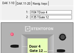
| T | Alphanumeric text | "T" is used to customize the text in the DAK display of the DualDisplay station. "T" can also used to add text labels on the navigation buttons of the IP Stations with display.
Example DualDisplay station:
|
| M | M - key | "M" generates a M-key on/off pulse, as if you have pushed the M-key briefly (0.3 seconds). Note that it will not generate M-key ON while the DAK key is pressed, and M-key OFF when released, but a short pulse when pressed. Examples:
|
| C | C - key | "C" generates a C-key on/off pulse, as if you have pushed the C-key briefly (0.3 seconds). Example:
|
| > | reference DAK of given Phys. no | ">" is used to "borrow" DAK keys from other, unused stations. Because each station has DAK tables for maximum 20 DAK keys, and some stations (e.g. CRMV, ECPIR-3P, DualDisplay stations) may have more than 20 DAK keys, one can use the ">" character to point to another station and use that stations DAK table. Example:
See also DAK redirection for CRM-V and DAK redirection for ECPIR-3P with expansion module EBMDR-8 |

|
|
Group Excl
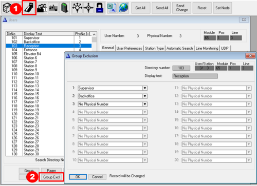
With Group Exclusion (aka Voice Paging Exclusion) each subscriber may exclude up to 20 neighboring stations from receiving the audio during a Group Call or Simplex Conference initiated by this subscriber. This feature is used to prevent acoustic feedback when stations located close to each other are members of the same group call or simplex conference.

|
|
Phone
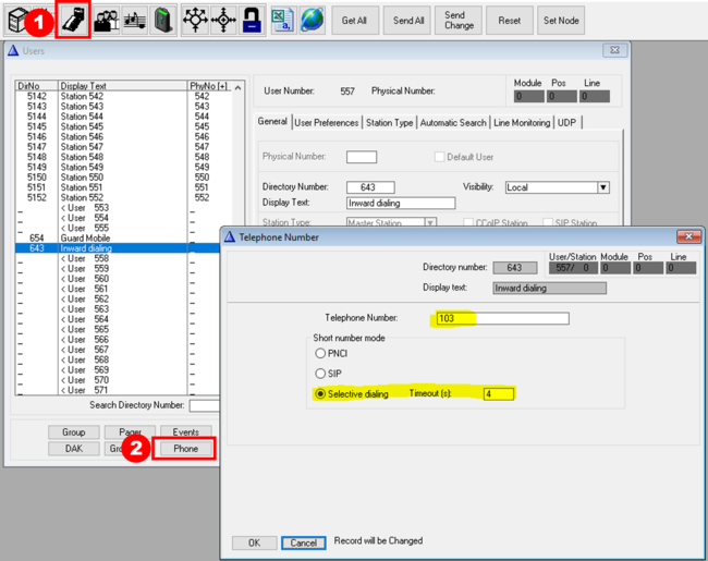
It is possible to define Short Numbers for external telephone calls. A "short Number" can be used for outgoing phone calls or for incoming phone calls:
- Outgoing phone calls: A "Short Number" is typically a 2- or 3-digit number, and when dialed you will be connected to an external phone line, and a preconfigured phone number is dialed.
- Incoming phone calls: An incoming call from a SIP trunk can be routed to the Short Number. When calling the Short Number a new dial tone will be heard. If the user starts dialing, the dialing procedure will be regular. If no dialing within the preset time, the call will be routed to a preconfigured number.
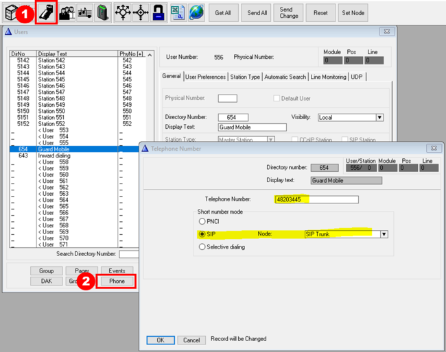
To create a Short Number, select a user 553 or higher, then select the Phone button.
- Short Number configuration
- Telephone Number: The number to call when the Short Number is dialed. Maximum 18 digits
- Short number mode: There are thre modes. "PNCI" and "SIP" are used for outgoing telephone calls, while "Selective dialing" is used for incoming telephone calls.
- PNCI: Shortnumber configuration for outgoing calls via the PNCI telephone interface. Enter the telephone number to be dialled, and select the hunt group in which the PNCI is a member (normally group 50)
- Telephone Group: Here you select the group which is used to include all phone lines reached by dialling prefix 0, (group 50)
- SIP: Shortnumber configuration for outgoing calls via SIP Trunk line.
- Node: Select the SIP Trunk node that the call should be routed to. Note: Will work only when the SIP Gateway is configured to use 'one-stage' dialing. Configuration example here.
- Selective dialing: Can be used for two-stage incoming calls from SIP trunks. When calling the Short Number a new dial tone will be heard. If the user starts dialing, the dialing procedure will be regular. If no dialing, the dial tone will time out and the directory number stored as "Telephone number" will be activated. This feature is useful when calling in to the AlphaCom via a SIP gateway. The SIP gateway can be configured to call this Short Number which makes it possible to do selective dialing, or be transfered to a preset number if no dialing
- Timeout: If no digits are received within the set time, the call will be routed to the "Telephone number"
- PNCI: Shortnumber configuration for outgoing calls via the PNCI telephone interface. Enter the telephone number to be dialled, and select the hunt group in which the PNCI is a member (normally group 50)
See also the article Short Numbers.


