Exchange & System (AlphaPro)
From Zenitel Wiki
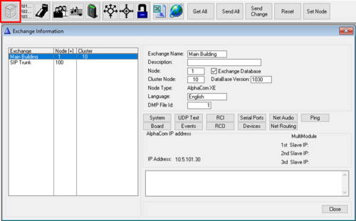
From the Exchange & System window you can inspect and modify a large number of system parameters.
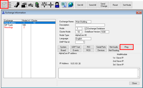
Exchange and System - Main window
- Exchange name: The name was choosen when the database was created. Can be edited from the "System" window.
- Description: Additional description may be entered. Note that this text is not transferred to the AlphaCom server. It is stored locally on the PC only. Can be edited from the "System" window.
- Node: 1 - 254. Default node number is 1. The node number is used for communication between AlphaCom servers in AlphaNet. The node number was choosen when the database was created. Can be modified from the "System" window.
- Exchange Database (In earlier AlphaPro versions: "AlphaNet - Adm. here"):
- Enabled: The exchange was created with full database.
- Disabled: The exchange was created without database. Used if there is a need to create routing to a remote AlphaCom server without having full database in this AlphaPro.
- Cluster Node: Cluster programming is an option to simplify programming and updating of numbers in AlphaNet when operating with integrated number series. Nodes with the same Cluster Node Number (1-255) are members of the same cluster.
- Database Version: The FoxPro database version used by the AlphaPro program. The information is automatically entered.
- Node Type: Reflects the choice you made when you created the exchange. It is possible to change node type in the "System" window.
- Language: Reflects the language choosen for display texts in stations when the database was created. Once the database is created, the langauge cannot be changed from AlphaPro.
- DMP File Id: The name of the dmp file is DMP_x.DMP, where x is the DMP File Id.
- AlphaCom IP Address: Shows which IP Address the AlphaPro program will try to connect to when establishing communication with the AlphaCom server
- MultiModule 1st/2nd/3rd Slave IP: Shows the IP address of the slave module(s) when MultiModule is used. If the Node Type is set to AlphaCom (and not AlphaCom XE) it will change slightly, and instead show which modules are enabled.
- Comments field: Additional comments may be entered. Note that this text is not transferred to the AlphaCom server. It is stored locally on the PC only. Can be edited from the "System" window.
System
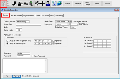
General
- Exchange name: The name was choosen when the database was created. Can be edited from the "System" window.
- Description: Additional description may be entered. Note that this text is not transferred to the AlphaCom server. It is stored locally on the PC only. Can be edited from the "System" window.
- Node: 1 - 254. Default node number is 1. The node number is used for communication between AlphaCom servers in AlphaNet. The node number was choosen when the database was created. Can be modified from the "System" window.
- Cluster Node: Cluster programming is an option to simplify programming and updating of numbers in AlphaNet when operating with integrated number series. Nodes with the same Cluster Node Number (1-255) are members of the same cluster.
- Node Type: Reflects the choice you made when you created the exchange. It is possible to change node type in the "System" window.
- Exchange Database (In earlier AlphaPro versions: "AlphaNet - Adm. here"):
- Enabled: The exchange was created with full database.
- Disabled: The exchange was created without database. Used if there is a need to create routing to a remote AlphaCom server without having full database in this AlphaPro. The remote AlphaCom must then be configured from a different AlphaPro PC.
- Language: Reflects the language choosen for display texts in stations when the database was created. Once the database is created, the langauge cannot be changed from AlphaPro.
- DMP File Id: The name of the dmp file is DMP_x.DMP, where x is the DMP File Id.
- Database Version: The FoxPro database version used by the AlphaPro program. The information is automatically entered.
- AlphaCom IP Addresses:
- Connect to: Specifies which IP address the AlphaPro PC should connected to when establishing communication with the AlphaCom
- Eth0: The IP address of ethernet port 0 of the AlphaCom (Default 169.254.1.5)
- Eth1: The IP address of ethernet port 1 of the AlphaCom (Default 0.0.0.0)
- AlphaNet: Enable this flag if the ethernet port is used for AlphaNet communication. When enabled the ethernet port will show up as a choice in the NetRouting window.

|
The AlphaCom IP addresses are configured from AlphaWeb, not from AlphaPro. |
- Username: The username needed to log in to the AlphaCom (Default admin)
- Password: The password needed to login to the AlphaCom (Default alphaadmin)
- Show Password: Check this box to view and confirm that the correct password is entered.

|
If no username and password is written here, AlphaPro will ask for credentials each time communication is established with the AlphaCom |
- MultiModule 1st/2nd/3rd Slave IP: Configure the IP address of the slave module(s) when MultiModule is used.
- Comments field: Additional comments may be entered. Note that this text is not transferred to the AlphaCom server. It is stored locally on the PC only. Can be edited from the "System" window.
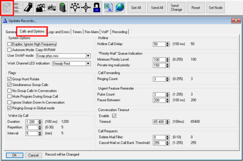
Calls and Options
System Options
- Duplex: Ignore High Frequency: Applicable to analog ASLT stations only. The high frequency evaluation in the duplex algorithm can be switched off by setting this flag. This may be useful in surroundings with high frequeny noise from fans or aircondition, as the high frequecies might influence on the duplex voice switching.
- Autonom Mode: Copy NVRAM: Applicable to MultiModule system only. The configuration of the Master AMC-IP board will be copied in the background to the slave AMC-IP boards. The slave modules will then be able to run in autonomy mode in case of communication failure with the master module. The copy process takes approx. 38 hours.
- User SWAP Mode. The options are:
- Swap phys.nos: After the swap Dir.no A calls Station B, Dir.no B calls Station A
- Copy users, names, dir.nos: After the swap Dir.no A calls Station B, Dir.no B calls Station A
- Copy users, names, NOT dir.nos: After the swap Dir.no A calls Station A, Dir.no B calls Station B
- Work Channel LED indication: When using the "Work Channel" option in the MultiConference feature, you can choose LED indication in the DAK key assigned as the current "Work Channel"
Flags
- Group Hunt Rotate: The Group hunt can be programmed either to:
- Enabled (default): Rotating order - start on the next physical number in the group in relation to the previous connection
- Disabled: Fixed start - always start at the lowest free physical number in the group
- Simultaneous Group Calls:
- Enabled (default): Several group calls might be active at the same time if there are no overlapping members. When several group calls are active simultanously, a group call can only be answered from a station belonging to the group. Note that the "gong" is a common resource for all groups and can only be used by one group at the time.
- Disabled: It is not possible to have more than one active group call in the system at a time.
- No Group Calls In Conversation:
- Enabled: No group call audio will be played in the station if it is active in a conversation.
- Disabled (default): Group call audio will be mixed with the conversation audio.
- Mute Program During Group Call:
- Enabled: Audio Program will be muted while a group call is being played
- Disabled (default): Audio Program will be mixed with the group call audio
- Ignore Station Down In Conversation: The system is designed such that if a station is reported faulty while in conversation, the conversation will be cancelled. With this flag enabled, the system will ignore station faulty reports for stations in conversation. This might resolve a problem experienced with some old analog ASLT substations that automatically cancels the call immediately after the call is connected. This flag is applicable to analog ASLT stations only.
- Ringing Group in Global mode:
- Enabled (default): The activation of a ringing group call is sent as broadcast to all nodes in AlphaNet. This implies that the same local Ringing Group number is activated in all nodes. See Ringing Group Feature in AlphaNet
- Disabled: The activation of a ringing group call will ring to the local ringing group in own node only
Wake Up Call
- Duration: Duration of private ringing for Wake-up Calls
- Repetition: Number of times the Wake-up Call is repeated if not acknowledged
- Interval: The time between repetitions
Hotline
- Hotline Call Delay: The time from the handset is lifted till the hotline number is dialed. During this time it is possible to use the keypad for ordinary dialing. If all telephones/stations with the hotline option are going to be used for hotline dialing only, set the delay to 0. Default time = 5.0 sec. The Hot-Line feature must be enabled per station in the Users & Stations > Station Type window.
Priority Mail" Queue Indication
- Minimum Priority Level: This value is linked to the events Priority Mail Present and Priority Mail in Idle, and sets the minimum priority level required to trigger these events. By default these events are triggered by mails or call requests with priority 100 or higher.
- Private ring mail priority: When receiving Mail or Call Request with this priority or higher, the receiving station will be alerted by a private ringing tone. Default priority level is 150 or higher. Also ATLB subscribers (telephones) can receive this type of Call Requests, as the telephone will start to ring when a call is received.
Call Forwarding
- Ringing Count: When Call Forwarding is activated on a station, this parameter sets the number of ringing signals to be played in the station before the call is forwarded. When set to 0 the call will be forwarded immediately, without any ringing signal heard in the station.
Urgent Feature Reminder
- Pulse Count: The number of "dut-dut-dut-dut" tones when receiving Call Request (or any other mail) with priority 120 or more. Usually triggered by the call request code 622. See also Urgent feature reminder
- Pause Between: The interval between the Urgent feature reminder tones
Conversation Timeout
- Enable: By default converations are cancelled after 1 hour 49 minutes. Uncheck this flag if conversation timeout is not wanted. The timeout is applicable to point to point calls and Duplex conference calls. Simplex conference or Group Calls are not affected by this timer.
- Timeout: The conversation timeout can be modified. Max. time is 6540,0 seconds (1 hour 49 minutes)
Call Requests
- Delete Mail Filter: If the Delete Mail Filter is set different from "0", all mails or call requests with priority levels ending with this value (e.g. 3, 13, 23, 33, 43, etc.) can not be deleted from the station (i.e. dialing 7630 or 70+0), or by the $DELM data protocol command. If Delete Mail Filter = 10 then the filter is done on priority levels ending with 0. Mails will be deleted when successfully calling back to the sender, or when using the data command $CANM. Delete Mail Filter = 0 means all mails can be deleted.
- Cancel Mail on Call Back Threshold: Mails with priority higher than the set value will not be deleted when calling back. The mail/call request will remain in the queue. Can be used in combination with the Delete Mail Filter to prevent cancellation of call requests on the receiving station. Mails can be deleted by the data command $CANM.
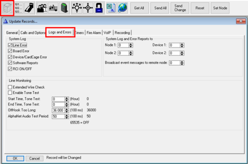
Logs and Errors
System Log It is possible to filter away certain error reportings to the System log
- Line Error: Station errors, both analog ASLT stations and IP Stations. (Station errors will still be reported via Event 13 - Faulty Station Line, and to Supervisor station defined in "Faulty Line" in Faults menu).
- Board Error: Errors on feature boards (ASLT, ATLB-12, AGA, ASVP) detected by the AMC-IP
- Device/CardCage Error: Includes the following devices:
- RIO (Devices 1 - 64)
- Exchange Modules (device 65-68) in a MultiModule system
- Software Reports: Some messages during start-up and normal operation
- RCI ON/OFF: RCI inputs located on the AlphaCom server or on a RIO unit
Line Monitoring
- Extended Wire Check: Applicable to analog ASLT stations only. Check for break in c- or d-wire even if ab-wires are OK. When a station is tested the LED will flash for a short period. A break in c/d-wire will be detected within approx. 1.5 to 6 minutes, depending on the number of stations connected to the system. Stations are tested one by one in a rotating fashing. The test uses 0.5 sec per station connected and 0.1 sec per station not connected. After having tested the last station in the loop there is a 23 second delay before the test starts again from the beginning.
- Enable Tone Test: Activate the periodic Tone Test. The manual tone test can be activated independent of periodic tone test.
- Start time, Tone Test: Enter the time (24-hour notation) when the tone test should start
- End Time, Tone Test: Enter the time (24-hour notation) when the tone test should stop. If start and stop time are set to 0, the tone test runs continuously.
- OffHook Too Long: Applicable to all types of stations (analog ASLT stations, ATLB phones and IP Stations). A station error is reported if the handset is off for more than the time specified here (default 1 hour), and no dialling takes place. OffHook error will also be reported on analog ASLT stations without display electronics if there is a break in the a- or b-wire.
- AlphaNet Audio Test Period: Interval between tone test of each AlphaNet audio line. Applicable only when AlphaCom servers are interconnected using AGA or AE1 boards, not when interconnecting servers using IP network. Value 65535 will disable the test. Disabling may be necessary in installations with multiplexes with echo cancellation or heavy voice compression, where the tone test may fail and cause an AlphaNet line error.
System Log and Error Reports to
- Node 1: and Device 1:: When an AlphaCom server generates an error message, it can be sent to one or two destinations. Enter the node and device number to which System log events should be sent. Default value is 0 + 0, which means report to own log port. Example: 4 + 65 means forward system log events to node 4. Messages forwarded by this programming are STATUS_REPORT and LOG STRING.
- Node 2: + Device 2:: Forward System Log reports to remote node and device. Default value is 0 + 0, which means report to own log port. Example: 4 + 65 means forward system log events to node 4.
- Broadcast event messages to remote node: ACDP broadcast messages will be forwarded to the specified node. Useful for Call Handler applications like AlphaVision used in AlphaNet, which relies on status information received from each individual AlphaCom exchange.
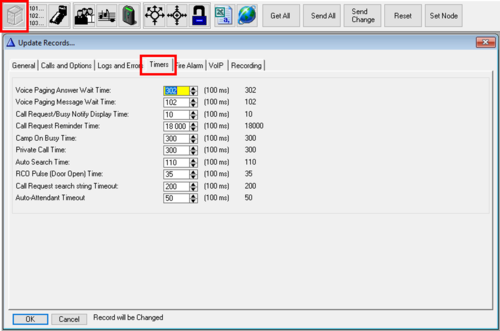
Timers
- Voice paging answer wait time: Answer time after a Group Call or All Call. The group call originator can choose not to cancel after the announcement, but wait for somebody to dial the answer code (default 99).
- Voice Paging Message Wait Time: Time from a Group Call or All Call is made till the M-key must be pressed.
- Call Request/Busy Notify Display Time: The time a Call Request Message or a Busy Notify Message is displayed at the receiving station.
- Call Request Reminder Time: Sets the timeout for the ringing for stations that have made a Call Request, or initiated a call to a Ringing Group
- Camp On Busy Time: When calling a busy station or a feature, you can wait (not cancel the call) and get automatically connected if the busy station or feature becomes free within this preset time (default 30 seconds).
- Private Call Time: Sets the timeout for the ringing for calls in Private Ringing mode.
- Auto Search Time: A call in private ringing mode will be transferred to the "Search list" of the called station after this time (default 11 seconds). The Automatic Search feature has to be enabled.
- RCO (Door Open) Pulse Time: The event types Door Opening during connection and Automatic lock are using this timer. When these events are triggered, the event is reported ON, and then OFF 3.5 sec (default) later. This is typically used to trigger and RCO/relay to generate a pulse for door opening. The pulse time can then be modified by this timer.
- Call Request search string Timeout: An unattended Call Request will be transferred to the "Search list" of the called station after this time (default 20 seconds). The Automatic Search feature has to be enabled.
- Auto-Attendant Timeout: The Auto-attendant feature provides voice guided menus for handling incoming phone calls. If the caller doesn't press any digits when calling in, the call will automatically be re-routed (default) after the voice message has finished playing. This timer sets the timeout before re-routing.
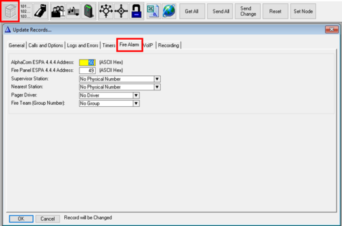
Fire Alarm
See Fire Alarm interface via ESPA444
- AlphaCom ESPA 4.4.4 Address: Link address in the ESPA 4.4.4 protocol for communication for AlphaCom. Is used for communication between AlphaCom server and the Fire Alarm Control Panel. The value is by default set to 50.
- Fire Panel 4.4.4 Address: Link address in the ESPA 4.4.4 protocol for the fire alarm panel. Is used for communication between AlphaCom server and the Fire Alarm Control Panel. The value is by default set to 49.
- Supervisor Station: The station receiving the pre-alarm message.
- Nearest Station: When a prewarning message is displayed at the supervisor station, pressing 8 at the supervisor station sets up a connection to the station closest to the Fire Alarm Control Panel.
- Pager Driver: The following options are available:
- Tateco T940SI (Driver 1)
- Ericsson PSP800 (Driver 2)
- Stentofon/Multitone RPE 351/651/Mk7 (Driver 3)
- Fire Team (Group Number): The group of intercom stations receiving the Fire Pre-Alarm and the Fire Alarm messages.
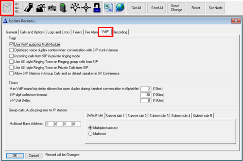
VoIP
Flags
- Use VolP Audio for MultiModule: The flag is enabled by default. When enabled, MultiModule calls will use AGA or AE1 for audio distribution between the modules if available. If no (free) AGA/AE1 found, VoIP channel will be used. When the flag is disabled, MutliModule calls will only use AGA or AE1 for audio distribution, VoIP channels will not be used.
- Optimized voice duplex control when conversation with SIP trunk/station: When an analog ASLT station in a noisy environment is calling a SIP phone there can be issues with the automatic voice switching (duplex) due to the echo cancelling in the SIP phone. When this flag is set, the initial voice direction is forced to be from the intercom station towards the SIP phone. When the phone operator starts to speak, the voice direction will switch towards the intercom station, regardless of the level of the audio signal from the intercom station. As soon as the phone operator stops speaking, the voice direction will switch back to the initial direction.
- Incoming calls from SIP in Private Ringing mode: When enabled, incoming SIP trunk calls will be forced in private ringing mode, regardless of the private/open setting of the intercom station.
- Use UK style Ringing Tone on Ringing Group Calls from SIP: When enabled, SIP trunk calls to a Ringing Group will be using a dedicated ringing tone. This is to distinguish external phone calls from internal calls.
- Use UK style Ringing Tone on Private Calls from SIP: When enabled, SIP trunk calls to a station in Private mode will be using a dedicated ringing tone. This is to distinguish external phone calls from internal calls.
- For the two options above, one can choose between different tone types:
- 500 Hz Tone
- 400 Hz Tone (Default)
- Private Ring Tone
- Attention Tone (muted)
- Attention Tone
- Busy Tone (muted)
- Busy Tone
- Dial Tone
- For the two options above, one can choose between different tone types:
- When disabled, regular Private Ringing tone will be used.
- Allow SIP Stations in Group Calls and as default speaker in SX Conference: (AlphaCom 12.3.3.1 or later) When the flag is enabled, SIP users can be included in "group" operations:
- Include SIP Stations or SIP Trunk Stations in group calls. The SIP phone must have AutoAnswer enabled. The system will wait for 3 seconds for a "SIP OK" response from the SIP phone. If no such response, the group call will carry on anyway. Maximum SIP users in a group call: 200 SIP users in ICX system, 50 SIP users in an AlphaCom system.
- A SIP user can be configured as a Default Speaker in a Simplex Conference. The SIP user must have AutoAnswer enabled. Use case: The SIP user is a conference circuit in a remote iPBX, in this way one can combine the conference of the iPBX with the simplex conference of the AlphaCom.
- SIP Stations (max 50) may receive Voice Alarm Messages. That is messages triggered by e.g. 761 code, $GM, AMG, AMS or $ALRM
- Make sure the Codec in the Group or Simplex Conference settings match the codec used by the SIP phone, or it might giver error code 488 Not Acceptable Here in the SIP trace.
Timers
- Max VolP round Trip Delay allowed for open duplex during handset conversation in AlphaNet: Applicable only for AlphaNet conversations involving analog ASLT stations using handset. This setting is used if there are more than 12 simultaneous handset calls (i.e. all LEC resources in the AMC-IP are in use).
- AlphaNet calls: The roundtrip delay on a VoIP AlphaNet conversation is measured by the AlphaCom. If the delay is more than the value specified in this parameter, a handset to handset conversation will be forced in voice switched duplex. This is to prevent echo in the handset due to crosstalk in AlphaCom handset (and no echo cancelling).
- SIP calls: When talking with handset conversation between Intergard station and SIP station the SIP station will get echo in the handset due to crosstalk in AlphaCom handset (and no echo cancelling). Due to this handset to handset communication will be forced in duplex. (Default delay setting for SIP = 30ms. Full duplex can be obtained if this parameter is adjusted to 40 ms or more)
- AlphaNet calls: The roundtrip delay on a VoIP AlphaNet conversation is measured by the AlphaCom. If the delay is more than the value specified in this parameter, a handset to handset conversation will be forced in voice switched duplex. This is to prevent echo in the handset due to crosstalk in AlphaCom handset (and no echo cancelling).
- SIP digit collection timeout: Specifies how long the AlphaCom should wait for more digits before setting up the connection to a SIP device. The timeout is used for "Enbloc dialing", i.e. by feature 81 and feature 83 when the parameter 2 field is used. See also SIP Trunk - access numbers
- SIP Dial Delay: This setting is applicable to "Overlap dialing" on SIP trunk. After a connection on the SIP trunk is established (i.e. SIP 200 OK is received), the sending of succeeding digits is delayed by the time specified by this timer.
Group Calls, Audio Programs to IP stations
- Multicast Base Address: By default this field is empty (0.0.0.0), and usually this default value can be used. When empty the multicast address 239.192.NN.0 will be used, where NN is the AlphaCom node number. The Multicast Base Address needs to be changed only if there is a conflict with other multicasting applications on the same net. If you enter a new Multicast Base Address, this address and up to 31 subsequent addresses will be used. The multicast addresses are used for group call, program conference and audio program to IP stations. See Multicast_in_AlphaCom for more details.
- Default rule: Determine how Group Audio is transmitted to IP stations. The default rule is a two-way choice:
- Multiplied unicast (default) - Audio is distributed by setting up one unicast connection to each of the stations in the group
- Multicast - Audio is distributed by sending the VoIP audio to a multicast address
- This rule applies to all IP stations which do not match any of the subnet rules 1 - 5.
- Subnet rule 1-5: Up to 5 Subnet Rules can be defined to make exceptions from the "Default rule". A Subnet Rule applies to IP stations with IP addresses within a given range. The IP address range for the rule is defined using the IP-address + subnet-mask scheme familiar from IP routing tables, see http://en.wikipedia.org/wiki/Subnetwork. A dropdown list with three alternatives tell how each of the 5 subnets are handled:
- Relayed multicast - the subnet forms a Relay Group
- Multiplied unicast
- Multicast
- After changing the Subnet Rules, AlphaCom has to be reset.
- When a station registers with the AlphaCom, AlphaCom checks the 5 rules in turn to find a address match. The search stops when the first match is found. This means that it is possible to specify a rule with a narrow address range, followed by a different rule for a address range which is superset of the first rule. Stations which do not match rule 1, but rule 2 will use rule 2.
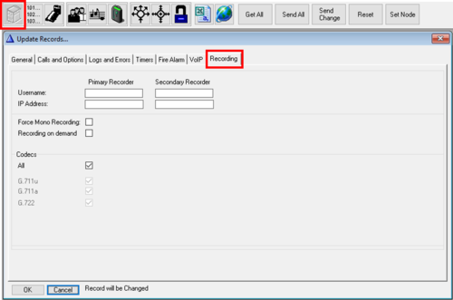
Recording
This window is used to configure audio recording. The audio recording is taking place on an external computer. AlphaCom communicates with the recorder using the SIP protocol. For more information, see the Recording category
- Username:
- Primary Recorder: Enter the registration name of the recorder in the Username field for the Primary Recorder
- Secondary Recorder: If there is a redundant recorder as well, enter its registration name in the Username field for the Secondary Recorder
- Redundant recording:
- As from ICX-AlphaCom 1.1.3.0, AlphaCom will record on both defined recorders in parallel
- For all other ICX-AlphaCom and AlphaCom software versions: AlphaCom will first attempt to record a conversation on the Primary Recorder but if that recorder is not available, the Secondary Recorder will be used.
- IP Address:
- Primary Recorder: Leave this field blank when using STENTOFON recording software. Only used when required by 3rd party recording software
- Secondary Recorder: Leave this field blank when using STENTOFON recording software. Only used when required by 3rd party recording software
- Force Mono Recording: Only used when required by 3rd party recording software. When enabled there will be a single SIP connection and RTP stream from the AlphaCom to the recorder. The RTP stream will contain audio from both parties in a conversation. When using STENTOFON recording software this flag should be disabled, causing two SIP connections and RTP streams from the AlphaCom to the recorder, allowing the user to listen to one or the other party in a conversation.
- Recording on demand: When the "Recording On Demand" is enabled, no recording will be activated in the system by default. All recording must be started with the $REC command.
- Codecs
- All: Enable (default) when all codecs are supported by the recording software (default for STENTOFON recording software). Disable only when required by 3rd party recording software to specify certain codecs.
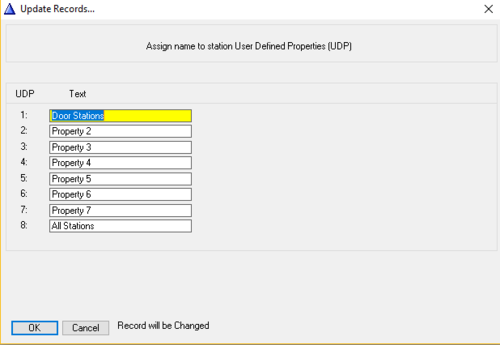
UDP Text
UDP Groups are used by the Event Handler to give common properties to a group of stations. Each UDP Group can be assigned a text to describe what the UDP Group is used for. This text will also appear in the Event Handler when refering to the UDP Group.
RCI
Inputs
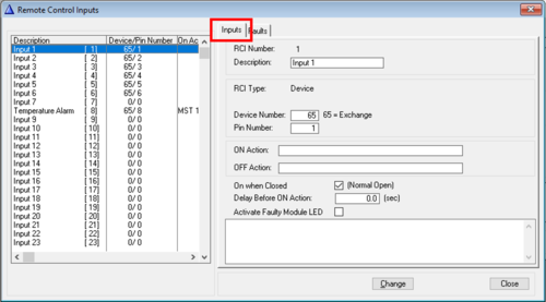
The Input window is used for configuration of inputs connected to AlphaCom XE servers, IPARIO units, RIO units and ENA Amplifiers.

|
Inputs on Turbine and INCA stations must be configured via the Event Handler, see Input from IP Stations |
- Description: Any text describing the usage of the input. Note that this text is not transferred to the AlphaCom server. It is stored locally on the PC only.
- RCI Type:
- Device: Use "Device" when the input is physically connected to an AlphaCom server or a RIO unit
- Device Number:
- 1 - 64 = External RIO unit. The device number is set by switch settings on the RIO board
- 65 = AlphaCom server
- 66 - 68 = AlphaCom Slave modules in a MultiModule system
- Device Number:
- Station: Use "Station" when the input is physically connected to an IPARIO unit or an ENA Amplifier
- Station Number: The physical number of the IPARIO or ENA Amplifier
- Device: Use "Device" when the input is physically connected to an AlphaCom server or a RIO unit
- Pin number: Each input is numbered from 1 and upwards:
- AlphaCom XE26/AlphaCom XE20: Pin numbers 1-6
- AlphaCom XE7: Pin numbers 1-2
- RIO unit: Pin numbers 1-8
- IPARIO unit: Pin numbers 1-6
- ENA Amplifier: Pin numbers 1-8
- Temperature alarm: Internal pin number 8 is the temperature alarm, which by default will send a "Temperature Alarm" message to the station on physical number 1, and write to the System log
- ON Action: Enter the action command to take place when the RCI input is turned on. It is possible to have several commands separated by semicolons <;>. Maximum 40 characters. If this is not sufficient the data command $ER can be used to trigger an event in the event handler, and the actual commands can be executed there.
- OFF Action: Enter the action command to take place when the RCI input is turned off. It is possible to have several commands separated by semicolons <;>.
- On When Closed: Generate alarm on closed or open contact
- Checked (default): Normal Open (NO) contact. The ON Action is activated when the contact closes, and OFF action when it opens
- Unchecked: Normal Closed (NC) contact. The ON Action is activated when the contact opens, and OFF action when it closes
- Delay Before ON Action: The time from the RCI is activated to the action is carried out. If the RCI in the waiting time is deactivated, the action is not carried out. Value is shown in 100 msec units. Maximum value 65 000 = 1 hour 48 minutes. This can be used for two purposes:
- Stabilizing of the line, to debounce any unwanted signals.
- Delayed call/alarm. For example, used with an alarm button in a lift. The button will have to be pressed down for a certain time to activate the alarm signal. Thus an unintended short press will be ignored.
- Activate Faulty Module LED: When enabled the Status LED in front of the AlphaCom XE20/XE26 will turn red when the RCI is activated (ON), and will go green when the RCI goes to OFF. Use case: Connect the Fault relay from the Power Supplies to an RCI input to indicate with the status LED if there is a power supply error.
Faults
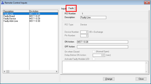
Fault reports, such as station errors, are by default sent to station on physical number 1. In this window you can change the receiver of such error reports, or you can remove the reporting.
Fault cases:
- Faulty Line: Triggered when there is a station error. All types of stations (IP Stations, SIP phones, analog ASLT stations and ATLB-12 phones) are monitored and reported
- Faulty Board: Triggered if there is an error on one of the AlphaCom feature boards ASLT, ATLB-12, AGA or ASVP.
- Faulty Device: Triggered if there is communication error between AlphaCom and a RIO unit, or between AlphaCom Master Module and a Slave Module in a MultiModule system
- Faulty AGA Line: Triggered if there is an error on an analog AGA line between AlphaCom servers in AlphaNet or MultiModule
- Description: Any describing text. Note that this text is not transferred to the AlphaCom server. It is stored locally on the PC only.
- ON Action: Enter the action command to take place when the specified fault occurs. It is possible to have several commands separated by semicolons <;>. Maximum 40 characters. If this is not sufficient the data command $ER can be used to trigger an event in the event handler, and the actual commands can be executed there.
- The default "ON Action" will send the fault reports to station 1.
- MST 1 0 28 means:
- MST = Mail to STation
- 1 = Physical number of station to receive the error report
- 0 = Filler (always use "0")
- 28 = Station Line error. Other codes are: 27 = Board error. 29 = Decvice error. 30 = AGA Line error.
- If the error reports should be sent to another station, simply change the first parameter. MST 23 0 28 will send Station Error reports to station 23.
- If the error reporting should be removed, simply delete the text in the "ON Action" field.
- OFF Action: Not in use.

|
|
Serial Ports
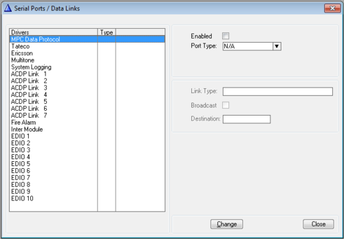
The Serial Ports/Data Links window lets you configure external communication using TCP/IP or serial link RS232 (or RS422/485).

|
In ICX-500 and ICX-AlphaCom Core the license "1002602400 ILI-IF" is required to enable these ports |
- Drivers: Available drivers/protocols are:
- MPC Data Protocol: The proprietary MPC Data Protocol. Used by some system integrators
- Tateco: Pocket pager - used for communication with pocket paging system using the ESPA 4.4.4 protocol
- Ercisson: Pocket pager - used for communication with pocket paging system using the ESPA 4.4.4 protocol
- Multitone: Pocket pager - used for communication with pocket paging system using the ESPA 4.4.4 protocol
- System Logging: Obsolete. Was originally used for connection of serial printer/PC for logging of error reports. Logging is now configured via the AlphaCom web interface
- ACDP Link 1-7 - The proprietary AlphaCom Data Protocol
- Avaliable Link Types:
- ISO1745 Point to Point - RIO,PC: Normally used for RS232 communication with the RIO unit.
- ISO1745 Multidrop - RIO: Normally used for RS485 (bus) communication with the RIO unit.
- Stentofon Link Layer - AlphaNet. Normally used for RS232 or RS422 communication with another AlphaCom in AlphaNet.
- Stentofon Multidrop Slave - Reserved. A master/slave protocol for special purposes
- Stentofon Multidrop Master - Reserved. A master/slave protocol for special purposes. Also used by AlphaVision.
- Stentofon Simple Link Layer - PC. The Stentofon Simple Link Layer is a point-to-point link layer which can be used as an operator interface. To get response messages back to the port, one must define at least one external device on this port. Enable "Broadcast" if ACDP broadcast messages should be transmitted.
- Broadcast: Enable "Broadcast" if ACDP broadcast messages should be transmitted.
- Destination: Any descriptive text. Note that this text is not transferred to the AlphaCom server. It is stored locally in the PC only.
- Avaliable Link Types:
- Fire Alarm - Used for connection to Fire Alarm Control Panels using the ESPA 4.4.4 protocol
- Inter Module - Proprietary protocol used for serial RS232 communication between AlphaCom modules in a MultiModule system. Note: Do not enable this port if MultiModule is interconnected via IP.
- EDIO 1-10:
- EDO (External Data Output) is a user definable ASCII text protocol intended for CCTV control, making customized logs etc. Up to ten EDO ports can be defined. EDO is controlled from the Event Handler where it can be configured to send free text merged with parameters for the active stations. Ascii control characters can be generated by using character escape codes.
- EDI (External Data Input) is used to receive ASCII text from external equipment. The input message must have a termination character. Maximum 128 characters. Parsing the content is done in the action string in the Event Handler
- Start Character (Optional): Enter the ascii descimal value of the start character to indicate the beginning of the string. The hex value of the character will show up next to the entry.
- Stop Character: (Must): Enter the ascii descimal value of the stop character to use to terminate the input string. The hex value of the character will show up next to the entry. Default value is 10 (= Line feed)
- Enabled: After enabling a driver/protocol, the AlphaCom have to be restarted for the change to takes effect.
- Port Type:
- Serial 0/1: When selecting serial port, additional parameteres become available:
- Bit Rate: 1200, 2400, 4800, 9600, 19200 or 38400. Parity: None, Even or Odd. Data Bits: 7 or 8. Stop Bits: 1 or 2.
- TCP/IP Server: When selecting TCP/IP Server, additional parameteres become available:
- Port: Specify which TCP port number the AlphaCom should listen to. Note that the port number also must be defined in the AlphaCom firewall. From AlphaWeb select System Configuration > Filters.
- Keep Alive: If there is no activity on a TCP/IP link, the link will time out and will be closed by the server. When "Keep Alive" is enabled, a KeepAlive message will be sent every 5 seconds to keep the link active.
- TCP/IP Client:
- IP Address: Enter the IP Address of the remote party in IPv.4 format (e.g. 192.168.0.5)
- Port: Specify which TCP port number to use for the connection.
- Keep Alive: If there is no activity on a TCP/IP link, the link will time out and will be closed by the server. When "Keep Alive" is enabled, a KeepAlive message will be sent every 5 seconds to keep the link active.
- Define when the connection should be established:
- Connect at AlphaCom startup (default) If the client disconnects, AlphaCom will try to reconnect immediatly.
- Connect at AlphaCom write
- Connect at AlphaCom write, disconnect after each write
- IP-ARIO: The IPARIO can be used as an Ethernet to Serial converter. The RS232 serial port of the IPARIO can be connected to external equipment, and the IPARIO converts the data from serial to IP, and communicates with the AlphaCom using TCP/IP. The communication parameters of the serial port in the IPARIO is configured in AlphaPro. The AlphaCom will forward these parameters to the IPARIO when the IPARIO goes online:
- Bit Rate: 1200, 2400, 4800, 9600, 19200 or 38400. Parity: None, Even or Odd. Data Bits: 7 or 8. Stop Bits: 1 or 2.
- Station: The physical number used in AlphaCom by the IPARIO.
- Port: Specify which TCP port number to use for the connection with the AlphaCom.
- Serial 0/1: When selecting serial port, additional parameteres become available:

|
|
NetAudio
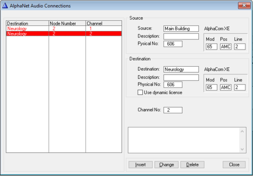
In the NetAudio window you can configure static (fixed) audio links between AlphaCom serveres (AlphaNet), and you can reserve VoIP Channels for SIP trunks.

|
Unless you are using AlphaNet Static license, you can normally leave the NetAudio table blank |
When to use the NetAudio table:
- The NetAudio table is not used used when:
- Using AlphaNet Dynamic license between AlphaCom servers in AlphaNet
- The NetAudio table might be used:
- If using AlphaNet Dynamic license between AlphaCom servers in AlphaNet, but want to reserve some VoIP channels to a dedicated AlphaCom server.
- If one want to reserve VoIP channels for a SIP Trunk, see Reserving VoIP channels for a SIP trunk for details.
- The NetAudio table must be filled in when:
- Using AlphaNet Static license between AlphaCom servers in AlphaNet
- Connecting AlphaCom servers in AlphaNet by means of AGA boards
- Connecting AlphaCom servers in AlphaNet by means of AE1 boards
Source
- Source:The name of the source node
- Description: This field is automatically filled in
- Physical No:The physical number used by the VoIP channel, AGA board or AE1 board in the source exchange
- VoIP Channels use virtual physical numbers: 605 - 634
- AE1 boards are using 6 physical numbers according to the board position, and in addition virtual physical numbers: 553 - 604
- AGA boards are using 6 physical numbers according to the board position: 1 - 138
- Mod/Pos/Line: This is automatically filled in, as a result of the chosen physical number
Destination
- Destination: The name of the destination node
- Description: This field is automatically filled in
- Physical No:The physical number used by the VoIP channel, AGA board or AE1 board in the destination exchange
- Mod/Pos/Line: This is automatically filled in, as a result of the chosen physical number.
- Channel No.: The audio channel number for the connection between the two exchanges. The channel number is an internal index number. Normally you use the channel number that AlphaPro suggests you to use. The same channel number might be reused towards different destination exchanges.
- Use dynamic license: Enable this flag if the destination node is using AlphaNet Dynamic license
See the AlphaNet article for some examples on how to configure NetAudio.
Ping
The Ping button gives the opportunity to test the network before trying to send data. It is also a quick and useful tool to check the network if AlphaPro is unable to communicate with the exchange.
If communication with the AlphaCom server cannot be obtained by pressing Get All, Send All or Send Change, then pressing the Ping button can give valuable information:
If the Ping test returns Successful, the network is ok. Check that the TCP port 60001 (which is used by AlphaPro) is open in AlphaWeb > Filter Settings.
If the Ping test returns Failed, it means the network connection with the AlphaCom server is not OK. Check these factors:
- Cable error
- The AlphaCom server is connected to the wrong ethernet port
- Your PC is not configured with an IP address in the same range
- AlphaPro is set to communicate with the wrong ethernet port
- AlphaPro is configured with the wrong IP address
- Ping is blocked in a network component (switch/router)
Board
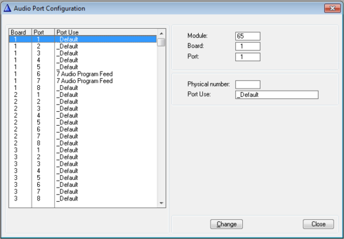
The Board table is used to modify the default behavior of the ports on AGA boards and ASLT boards.
- Module, Board, Port: Shows which Module (65 = AlphaCom), Board position (1-24) and Port number (1-8) according to the selection in the list box
- Physical Number: The physical position according to the selection in the list box.
- Port use: The following options are available:
- Default: Use the default Port Use.
- For ASLT boards the "Default" Port Use means that the port is used for Intercom Station.
- For AGA boards the "Default" Port Use depends on the board position in the module. In position 18-21 Audio Program is default, and in position 22-24 MultiModule audio is default.
- Open Duplex Conference Mixer: Obsolete. The AGA board could previosly be used for duplex (handsfree) conference mixing. In AlphaCom XE (and AlphaCom E) this is handled by the AMC-IP board itself.
- Station: Configure a port of the AGA board to behave as a "Station". You'll get 0dBm audio in and out. The port can be called to by its directory number, and it can be included in e.g. Simplex Conference and Group Calls. Useful for PA and Mobile Radio integration. Equivalent to ASLT + FBSAR.
- Multiconference Monitor: Obsolete. The AGA board could previosly be used for multiconference mixing. In AlphaCom XE this function is replaced by an IP based MultiConference feature.
- Audio Program Feed: A port of the ASLT or AGA board can be configured as an Audio Program input. By default physical numbers 5 and 6 in an AlphaCom XE7 are configured for Audio Program Feed. If these ports are to be used for intercom stations instead, the Port Use must be set to "Default". See Physical number 5 and 6 (AlphaCom E7) for more details.
- Reserved 5: Not in use.
- Reserved 6: Not in use.
- Default: Use the default Port Use.
Events
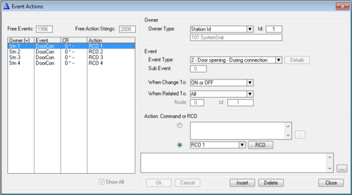
The Event Handler is based on the concept that when intercom functions run, they report 'events' to a part of the software called the Event Handler. The event can be described as a trigger that sets off an action in the system depending on the information entered here in AlphaPro.
Free Events: Shows how many events are free out of the total of 2000 events.
Free Action Strings: Each line of action commands count as one Action String. If the line is longer than 16 characters, it will count as 2 action strings. This field shows how many action strings are free out of the total of 2000 available action strings.
Show All: When checked, all events in the system will be shown, not only events for the particular station highlighted when the Event window was opened.
Owner. The owner is the source which triggers the event.
- Owner type. The options are:
- Station Id: A single station. The Id = Physical number of the station
- Stations w. UDP: A group of stations. The Id = UDP group 1 - 8
- Scheduler: Scheduler use the Realtime clock of the AlphaCom as event owner. Event can be configured to trigger at specified hours, weekdays or dates
- EDI Text Config: Trigger event when receiving text on an EDI port
Event
- Event Type: Select which event should cause the action. Here an overview of event types.
- Details: This button is enabled when choosing the Event Type: 1 - Audio. One can then choose which type of audio to trigger the event. See Audio_(Event_Type)
- Sub Event: Some events have a subevent which makes it possible to filter on more options than only the main event it self.
- When Change To: The action is executed at a specific event transition, i.e. when the defined event goes on and/or off. The options are:
- OFF - The event is triggered only when the event goes off
- ON - The event is triggered only when the event goes on
- ON or OFF - The event is triggered when the event goes on, and also when the event goes off
- When Related To
- All: The event is carried out with no check on the related number, i.e. works for all stations. Many events have no related number, and in that case the fields are not available
- Directory Number: The action is executed when the event owner is connected to the defined station or feature directory number. The id field has two parts:
- Node: An AlphaNet node number (0 = own server). ID: The Directory number of a station or feature
- Stations w. UDP: The action is executed when the event owner is connected to any station which is member of the specified UDP group. The Id specifies the UDP group 1-8.
Action Command or RCO
- When the upper radio button is selected, you can write action commands which will be executed when the event is triggered. One command per line.
- When the lower radio button is selected, you can select one RCO (Remote Control Output) to be operated by the event.
- The button RCO opens the RCO table, where you can map logical RCO numbers to physical outputs.
RCO
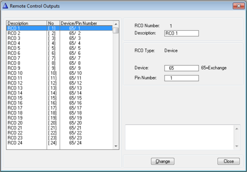
RCOs (Remote Control Output) are used for operation of relays for door opening, call indication etc. In the RCO table logical RCOs are mapped to physical outputs.
The physical outputs are given as:
- Device + Pin Number, or by
- Station + Pin Number.
- RCO number: The "logical" number (1-500) of the RCO. This number is used as parameter in the RCO command.
- Description: Any descriptive text may be entered. Note that this text is not transferred to the AlphaCom server. It is stored locally on the PC only.
- RCO Type = Station: The output is from Turbine device, INCA IP Station, IP-LCM Module, ENA amplifier or IPARIO unit
- Station: The physical number
- Pin number:
- Turbine Compact: Pin 1 - 7 (the relay is pin 7)
- Turbine Extended: Pin 1 - 10 (the relays are pin 7-8, extra relay via TA-10 unit is pin 9-10)
- INCA IP Station: Pin 1 - 2 (the relay is pin 1)
- IP-LCM Module: Pin 1 - 7 (the TKIS relay is pin 7). Pin 17-24 are the IP-LCM relays 1 to 8
- ENA Amplifier: Pin 1 - 6
- IPARIO unit: Pin 1 - 8
Devices
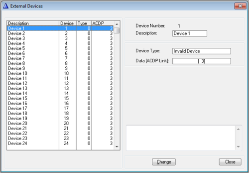
- Device Number: The device number is a unique address identifying the device (e.g. RIO, AlphaVision). The device number is a number between 1 - 64.
- Description: Any descriptive text may be entered. Note that this text is not transferred to the AlphaCom server. It is stored locally on the PC only.
- Device Type: There are five options:
- Invalid device: Default. No valid device connected.
- Unknown device: External computer with unspesific functionality. Can be used for any type of device using the AlphaCom Data Protocol ACDP
- RIO: Used by the RIO unit
- Control Handler: PC with call queuing features
- Operator (passive): Passive device, for Simple Link Layer terminal. AlphaVision uses this device type
- Data [ACDP Link]: The ACDP (AlphaCom Data Protocol) link used for communication with the device. The actual ACDP link is configured in the Serial Ports setup.
NetRouting
NetRouting is used to define the data and audio routing between AlphaCom servers (AlphaNet), and from an AlphaCom server to a SIP Trunk node.
Between AlphaCom servers one have to define the NetRouting in both directions. For SIP Trunking it is sufficient to define NetRouting from AlphaCom server to the SIP Trunk node.

|
Configuration of NetRouting for AlphaNet requires AlphaPro Professional (the USB hardware dongle must be present in the PC) |
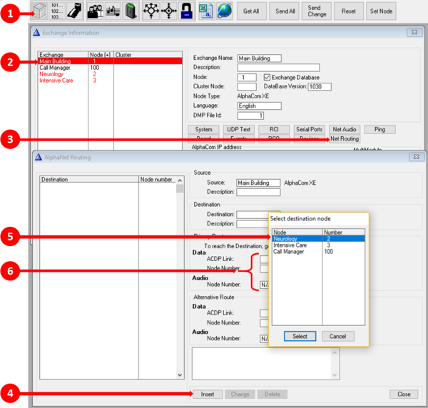
How to configure the NetRouting:
- From the AlphaPro main window, select Exchange & System
- Select the Source exchange from the list box to the left
- Select NetRouting
- Press Insert
- Select the Destination exchange from the list of exchanges that appeares
- Fill in Data and Audio routing under "Primary Route" as described below
Source
- Source: The source node for the route
- Description: Filled in by the system. The text is taken from the "Description" field in Exchange & System > System
Destination
- Destination: The final destination node for the route
- Description: Filled in by the system. The text is taken from the "Description" field in Exchange & System > System
Primary Route
- Data - ACDP Link: Select the link type used for the connection:
- Data over IP: For routing to another AlphaCom server over IP (AlphaNet)
- SIP Link: For routing to a SIP Trunk node
- ACDP Link 1-7: For routing to an AlphaCom server using serial (RS232) link
- RMD Link: Used when interfacing to a RingMaster CB901 system
- M100 Link: Used when interfacing to a M100 intercom system
- Data - Node Number: Data connection and signaling will be sent to the node specified here. Normally this is the destination node
- There is an option to send data signaling in transit via another node. Then enter the node number of the transit node here
- Audio - Node Number: Audio will be sent to the node specified here. Normally this is the destination node
- There is an option to send audio in transit via another node. Then enter the node number of the transit node here
- Data and Audio doesn't have to be sent to the same node
- Audio on IP: When checked, the audio is sent as VoIP over the IP network. Uncheck when using analog lines (AGA board) or E1/T1 trunk (AE1 board) for audio
Alternative Route
As an option it is possible to specify an Alternative Route in case the data connection on the Primary Route fails. Typically the primary route is configured to use an IP network on Ethernet Port 0, while the alternative route is configured to use a different IP network on Ethernet Port 1. It is also possible that one route is using ethernet, while the other route is using serial link and AGA or AE1 board.
Alternative Routing can also be used for SIP Trunking when there is a need for Failover to redundant SIP Server if the primary SIP server fails.
The configuration options are the same as for Primary Route:
- Data - ACDP Link: Select the link type used for the connection
- Data - Node Number: Data connection and signaling will be sent to the node specified here. Normally this is the destination node
- Audio - Node Number: Audio will be sent to the node specified here. Normally this is the destination node
- Audio on IP: When checked, the audio is sent as VoIP over the IP network. Uncheck when using analog lines (AGA board) or E1/T1 trunk (AE1 board) for audio
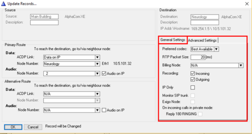
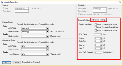
General and Advanced Settings
When configuring the NetRouting, there are some additional options available.
General Settings tab
- Preferred codec: Available options are: Best Available, G711u, G711a and G722.
- When creating NetRouting to an AlphaCom node (AlphaNet), "Best Available" is default. Normally you should not change this setting.
- When creating NetRouting to a SIP Trunk node, AlphaPro will import the codec setting from the SIP Trunk Node configuration. It is possible to override that configuration here. Set codec according to what is supported by the SIP Server.
- RTP Packet Size:
- When creating NetRouting to an AlphaCom node (AlphaNet), "20ms" is default. Normally you should not change this setting.
- When creating NetRouting to a SIP Trunk node, AlphaPro will import the RTP Packet Size from the SIP Trunk Node configuration. It is possible to override that setting here.
- Billing Node: AlphaCom has an embedded Billing Software module for access control and charging of external phone calls. When Billing is being used in an AlphaNet system, you need to choose by this setting in which node the Billing Module is running. Data about the external phone call will then be forwarded to this node for further processing.
- Recording: Each link has 2 audio recording flags associated with it, for incoming and outgoing calls. By default, both these flags are enabled. For the recording of AlphaNet calls, the rule is:
- Record incoming call if the Incoming flags for both the station AND the source node are enabled
- Record outgoing call if the Outgoing flags for both the station AND the destination node are enabled
- This makes it possible to select the side on which to record an AlphaNet call, or to have the option to record the call at both ends.
- IP Only: Set this flag if the Destination Node (B-node) is an AlphaCom XE1 ("IP Only") or ICX-AlphaCom, and the Source Node (A-node) is an AlphaCom XE7, XE20 or XE26 with analog stations. The flag will force duplex voice switching to take place in the Source Node where ASLT or ATLB-12 cards are present for the handling of the voice switching, which is required when analog stations are involved in a call. The flag will override the default behavior, which is to perform the voice switching in the Destination Node.
- It is not necessary to enable the "IP Only" flag when:
- Both nodes are AlphaCom XE1 or ICX-AlphaCom
- Both nodes are AlphaCom XE7/20/26 (with ASLT cards)
- Monitor SIP Trunk [SIP Trunk only]: When enabled, the AlphaCom will send the SIP message OPTIONS to the SIP server every 5 seconds, and expects a response in due time, else the link is reported down. The event 29 - AlphaNet Link is triggered when the communication with a SIP server goes up or down. See Monitoring a SIP Trunk for more details. The monitoring can also be used for Alternative Routing to Redundant SIP server.
- Exigo Node [SIP Trunk only]: Enable this flag if the SIP Trunk is used towards an Exigo PA system. In an AlphaCom - Exigo integration this flag will ensure a quicker (max 15 seconds) switchover of audio from A- to B-system in case the A-controller fails.
- When simultaneous AlphaNet setup from A and B Exigo Controllers, the overlapping B setup (Group Call or Audio Program to group) will be set in "Camp On" mode as long as A is active. If A fails, then B will continue to play. This assumes that Exigo A and B node is configured as odd/even-numbers according to rules found on ExigoWiki.
- On incoming calls in private mode: Reply 180 RINGING [SIP Trunk only]: By default the AlphaCom responds with the SIP message 200 OK on an incoming call to a station in private mode, and an audio connection is immediately established. When enabling this flag, the AlphaCom will instead first respond with 180 RINGING. When the called party answers the call, the audio connection will be established and the message 200 OK will be sent.
Advanced Settings tab
- Duplex switching: These settings are applicable only when analog ASLT stations or ATLB-12 telephones are involved in an AlphaNet call. By default the duplex voice switching takes place in the destination node (B-node). Default behavior can be modified by these settings.
- Avoid Duplex in Start Node: Inhibit use of duplex voice switching in the source node on AlphaNet calls to this destination node. This will force duplex switching in destination node also for IP-MultiModule and IP AlphaNet calls to traditional AMC ver. 8 or 9 systems.
- Avoid Duplex in Transit Node: This flag is used in mixed AlphaNet systems where there is a combination of AlphaNet over IP, and traditional analog (AGA/AE1) AlphaNet, and the end node is running AMC ver. 8 or 9. The flag must be set in the transit node where both the AlphaNet IP and AGA/AE1 are connected. The purpose is to force duplex to run in the transit exchange to avoid echo, as end nodes running AMC 8/9 do not handle delays on the audio link. (AlphaPro text says "Avoid Duplex in Transit Node", the correct is "Force Duplex in Transit Node")
- Force Duplex in Start Node: Force use of duplex voice switching in the source node (A-node) on AlphaNet calls to this destination node (B-node) for all node types. If AGA/AE1 is used, this flag will only work if source node number is lower than the destination node number. "Force Duplex in Start Node" is default behavior when calling to a SIP Trunk node, RM node or M100 node. Compared to the "IP Only" flag, The "IP Only" assume that all stations in the destination node can do echo cancellation, thus go open duplex when handset is lifted in source node
- RTP Delay: Jitter buffer size. Value 0 = Adaptive jitter buffer (recommended)
- Gain In: Range from -30dB to +30dB. 0=Use default value. Default value is 0dB gain for AlphaNet, and -6dB for SIP Trunk
- Gain Out: Range from -30dB to +30dB. 0=Use default value. Default value is 0dB gain for AlphaNet, and +9dB for SIP Trunk
- Limit In: Range from 3 to 36dB. 0=Use default value (= 0dB).
- Limit Out: Range from 3 to 36dB. 0=Use default value (= 0dB).
- Max VoIP Channels: The number of simultanous calls are limited by the AlphaNet license or the SIP Trunking license. In addition to this, it is possible to further limit how many VoIP channels a specific AlphaNet link or SIP Trunk should be able to use. This could be useful e.g. if there are multiple SIP trunks, and one might want to set restrictions on how many VoIP channels one particular trunk can use.

